I found this video of a Rotary lobe pump in linkedIn
Now I am intending to setup and run a simulation of a External Gear pump, So now What I need is to have a mass flow rate of in-compressible fluid in through the inlet and through the positive displacement of the spur gears the fluid would be pressurized and be flown out of the outlet, also the gears have to be shown rotating. So for this what type of boundary conditions what type of improvisations should I make
taking the video, link given above as reference
I agree with Jousef. The sim should not be too difficult with and MRF. However, I’ve only experienced usage of the MRF with circular enclosed solid bodies. The geometry of the gears in the rotary pump might make this simulation not very accurate unless you can assume that the gears act as a uniform circular rotating object which would be alright if it was at sufficiently high speed.
If the geometrical representation of the gears needs to be maintained and the flow interaction to be observed based on the shape of the gears as they rotate (usually at lower speeds) then this may be trickier to simulate. You may need to use AMI. I’m unsure if an enclosed but gear shaped MRF would work. What do you think Jousef?
For now, I would just assume the first paragraph and get things started.
Hi Jousef, I tried with adding MRF zones under the rotating zone for in-compressible fluid but an error occurred while running the simulation. I am sending the link of the project below for check
Hi Get_Barried, I tried with adding MRF zones under the rotating zone for in-compressible fluid but an error occurred while running the simulation. I am sending the link of the project below for check
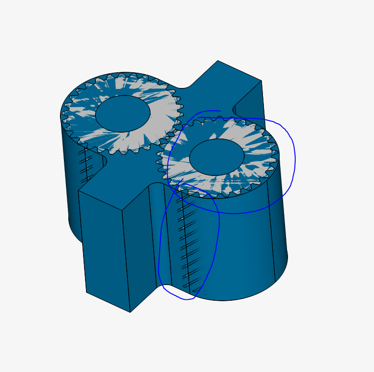
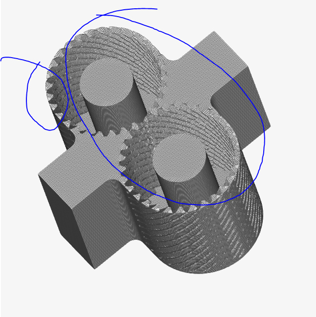
Your gears are sticking out of the body and the top surface has effectively zero thickness and is pretty much just an empty shell. Ensure the gears are enclosed fully and the top surface has some thickness and the gears are just mated to the body in an assembly. Refer to the mesh can you can see that the top surface was not even meshed due to the shell like nature of the top surface. In fact throughout the whole body, it is just an empty shell. I suggest having a certain thickness to the outer body to reduce these meshing problems as seen below.
Another issue is the obvious lack of an MRF rotating zone. To define a rotating zone you must have the gears inside a circular, enclosed, watertight solid zone as a separate part. If not you will encounter meshing problems and you will not be able to use an MRF let alone an AMI.
Resolve these issues in CAD first and we can proceed from there.
Hi Barry,
I made the correction needed which you had mentioned in our previous conversation. But I ain’t quite sure about the boundary conditions. Though I tried to run the simulation with the reference of the boundary conditions from centrifugal pump simulation. If you could check and review on the geometry and the boundary conditions when you are free
Though I ran the simulation for two times with the current boundary conditions, error stopped the run and no specific error info is shown whether machine memory is low or floating point error or anything
The issue here is the mesh, you have created a multi-region mesh which is required for CHT analysis but not incompressible. This means that the solids have also meshed and the regions for the MRF are not suitable. To fix this disable the ‘create multi-region mesh’ option, and define the MRFS using surface refinement with cell region checked. Also, for this type of mesh, this will be subjective to the material point, so ensure that is correctly defined.
gears are a type of cylindrical gear, with shafts that are parallel and coplanar, and teeth that are straight and oriented parallel to the shafts. They’re arguably the simplest and most common type of gear – easy to manufacture and suitable for a wide range of applications.
The teeth of a spur gear have an involute profile and mesh one tooth at a time. The involute form means that spur gears only produce radial forces (no axial forces), but the method of tooth meshing causes high stress on the gear teeth and high noise production. Because of this, spur gears are typically used for lower speed applications, although they can be used at almost any speed.
Spur gears can be made from metals such as steel or brass, or from plastics such as nylon or polycarbonate. Gears made of plastic produce less noise, but at the expense of strength and loading capability. Unlike other gear types, spur gears don’t experience high losses due to slippage, so they generally have high transmission efficiency. Multiple spur gears can be used in series (referred to as a gear train) to achieve large reduction ratios.