Aim is to simulate displacement controlled compression test conducted on UTM and get the reaction loads. Quarter model is being used to reduce time of computation.
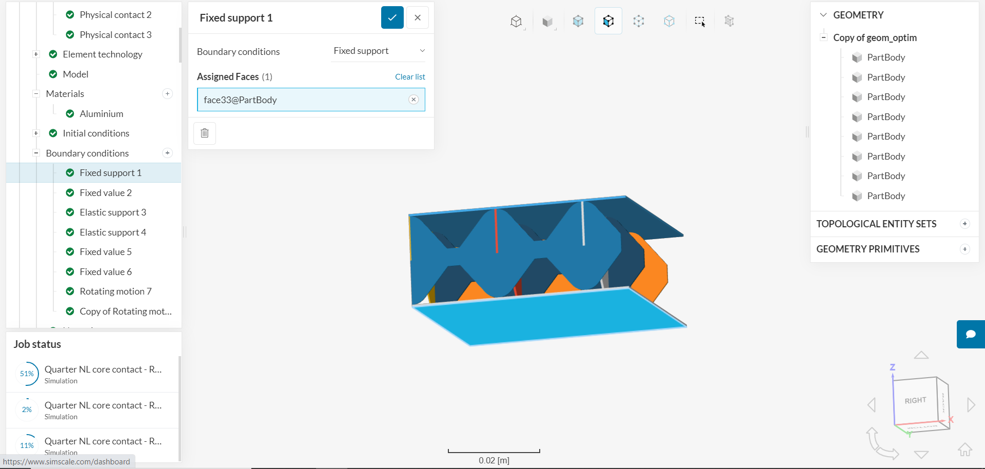
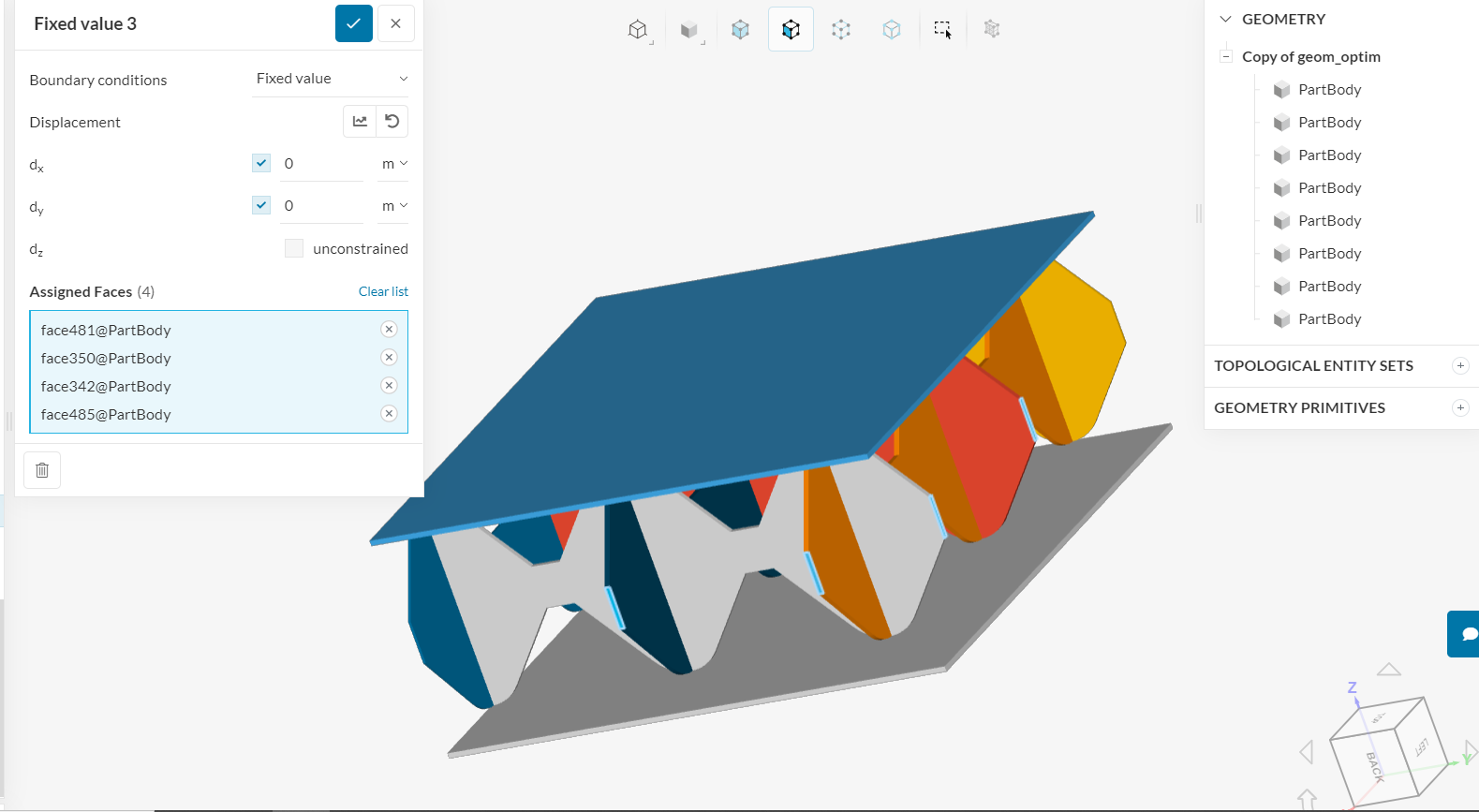
This is the fixed support setting. Bottom face is assigned.
Previously bottom plate was volume assigned (partbody). Changed to face assignment inorder to get non zero values of reaction ([reason for volume to face assignment])(Unexpected Reaction force results - #5 by tsite).
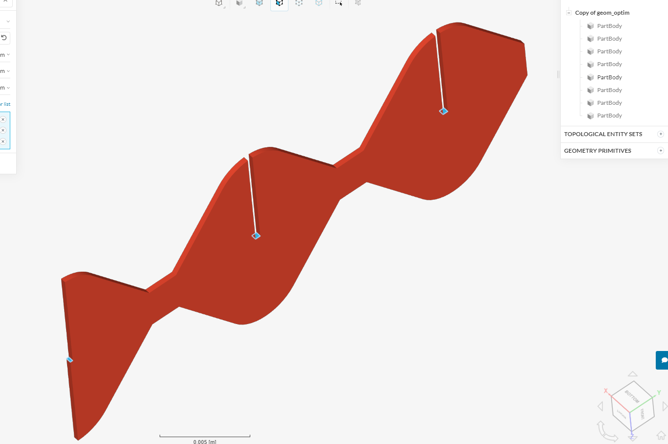
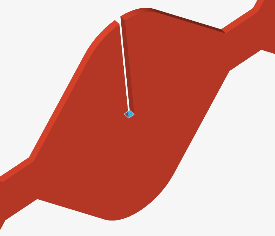
I am trying to reduce the complexity of the set-up by applying constraint on the horizontal face of the plate in the core of the sandwich(curved plates).
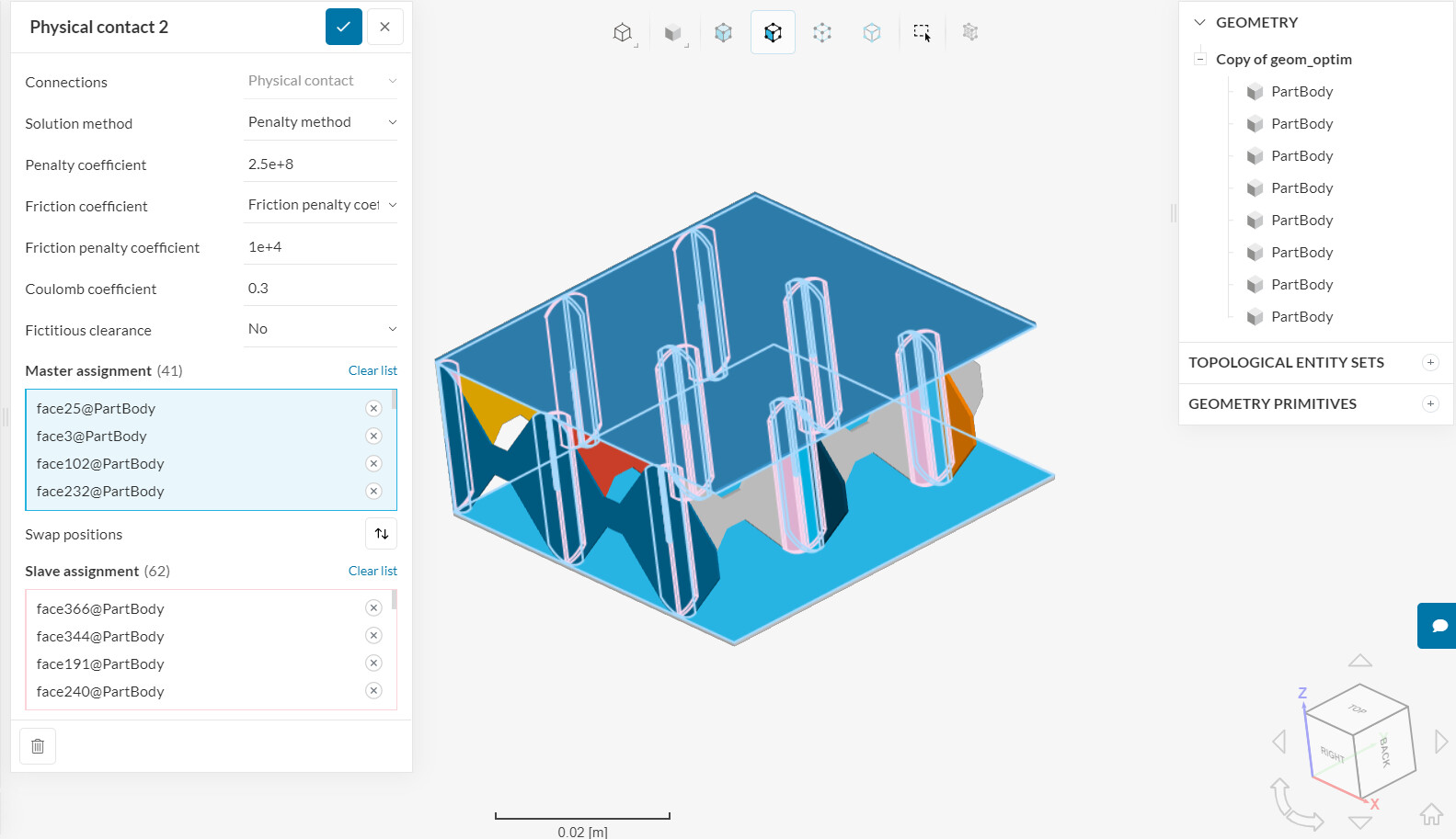
Contact between the core plates is non linear ( physical contact).
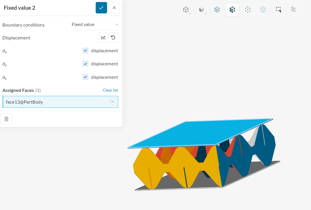
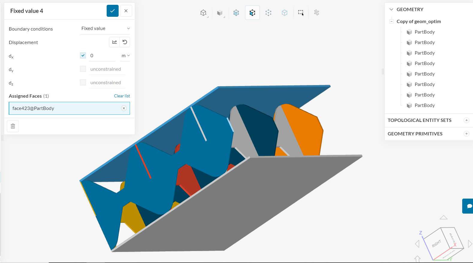
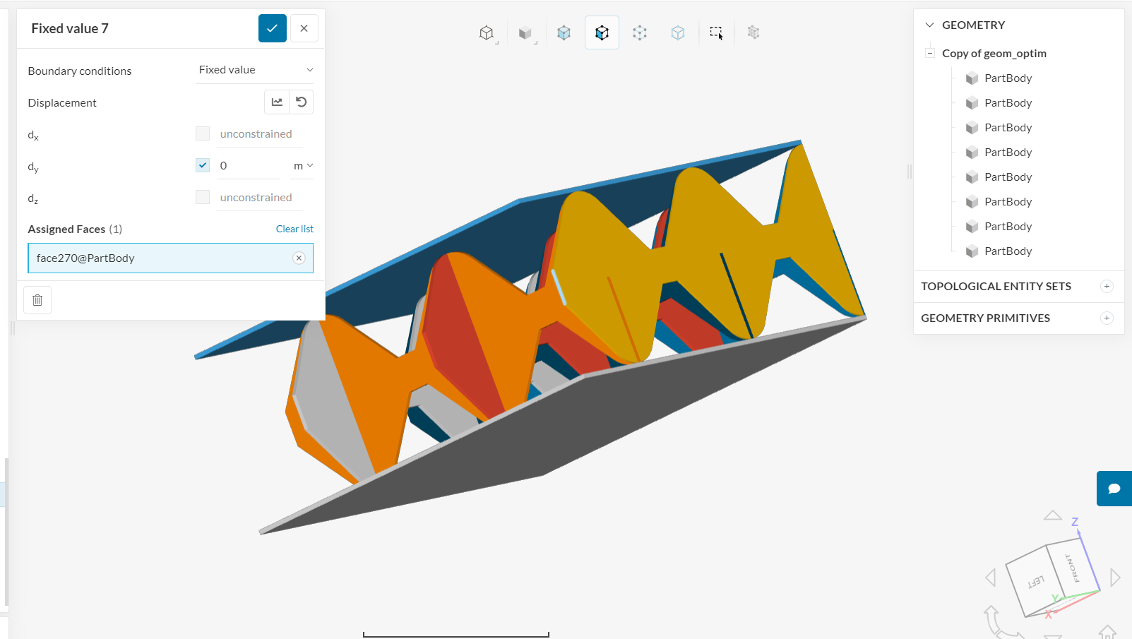
These faces have been chosen to be applied with boundary condition such that stay horizontal. Only one side of the core is chosen for this so as to not form singularity through over-constraint as contact is already present between such two faces between the cores.
I would like to know if the way i am doing it is correct.
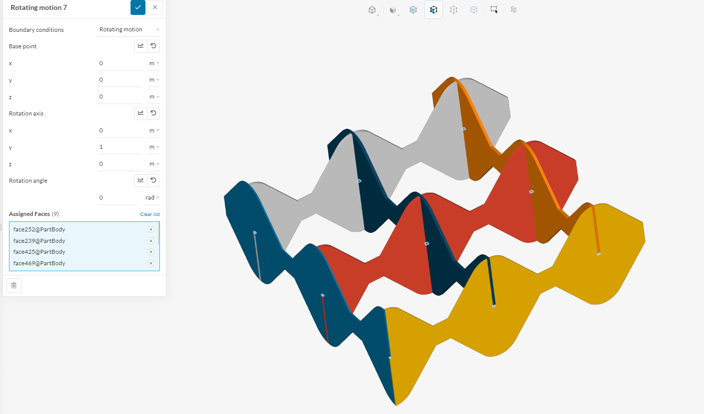
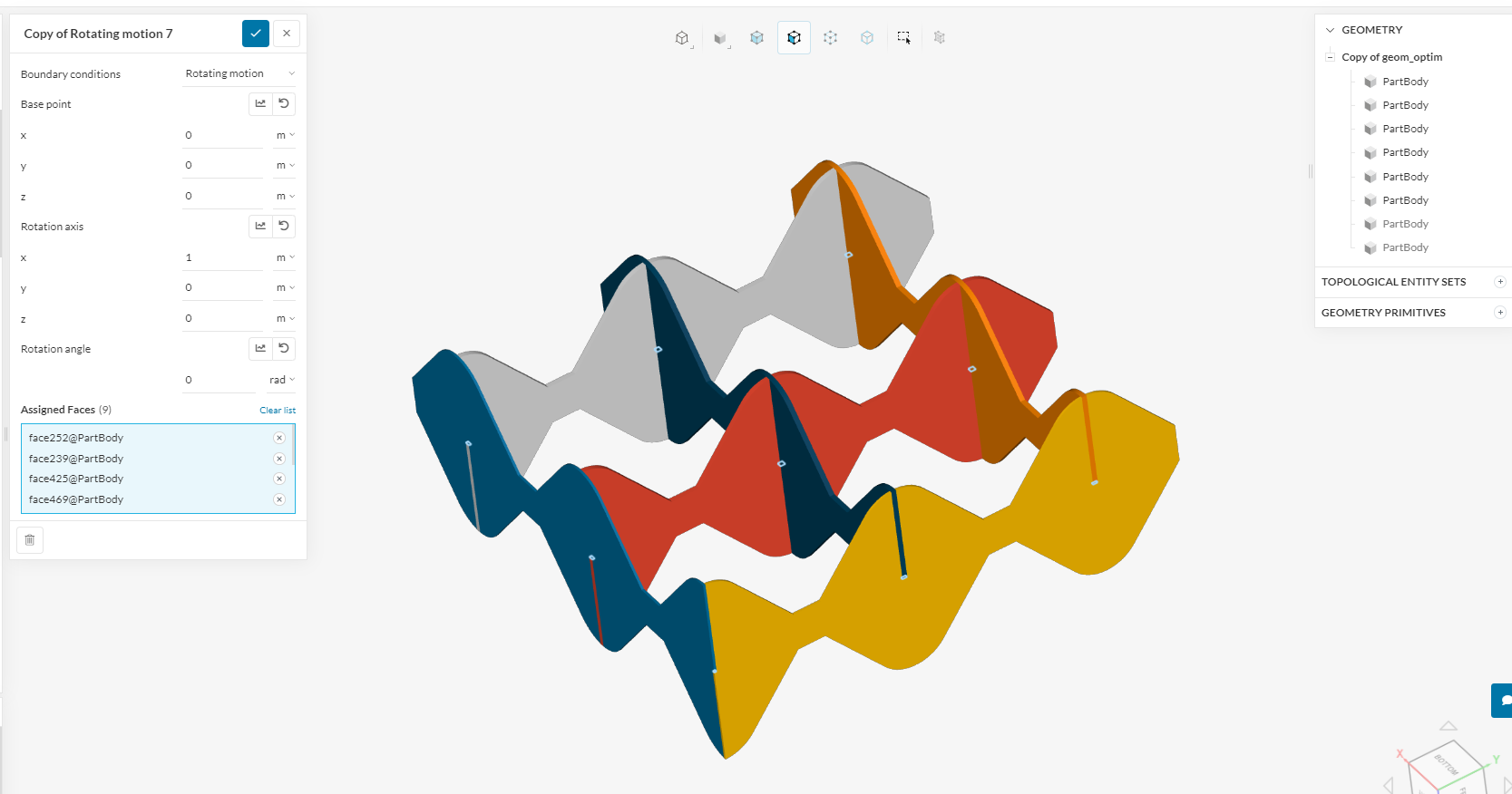
Rotation motion boundary condition applied on these faces with axis direction X and Y ( two different instances). Constant value of zero is given. Not sure about the base point though. How does this affect the rotation. Have chosen 0,0,0 to start with.
For run 35 the top core faces are chosen. For run 37 the bottom core faces are assigned for the above mentioned boundary condition.
Could I know if this boundary condition will keep the faces chosen horizontal throughout the simulation?
In run 36 have tried fixing the bottom horizontal faces of the core in the x and y direction , free in z. This is also another attempt to reduce complexity.
Hey Fillia,
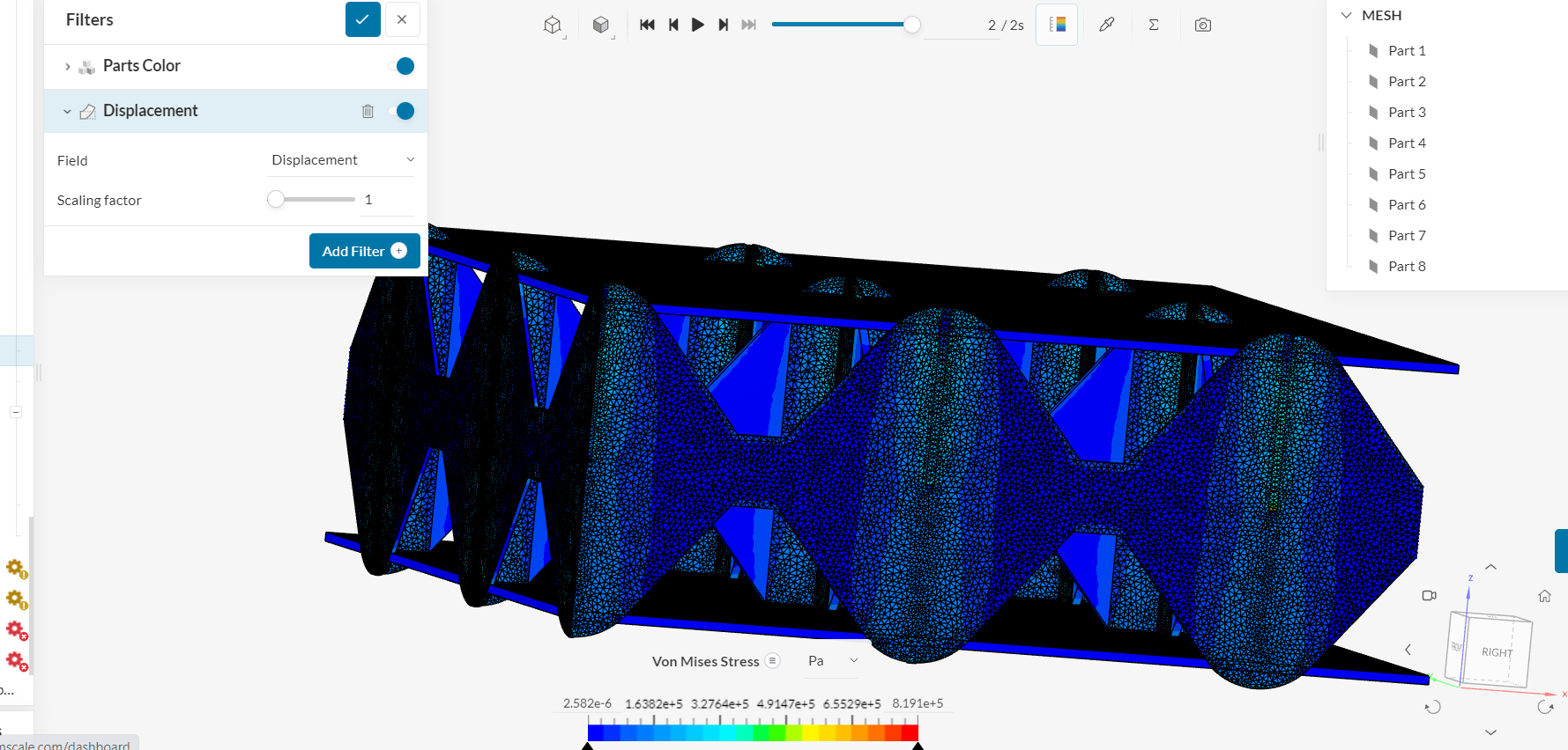
Run 35 36 37 have finished. Only 36 converged without error. Run 36 had the horizontal faces with fixed values ( x and y constrained to 0 and z free). The results give reaction at the supports and are too low ( of order 10^-3 compared to experimental data). Is the penalty coefficient the parameter to be changed to get higher values of reaction ( while keeping the material data same), or mesh refinement at the contact points? Would these help?
Going to try more methods to reduce complexity and shall get back to you soon.
Moreover the post processor shows a lot of penetration.
Fixed value 4 and 7 are given constraint only in one direction so as to not cause over constraint with fixed value 5 and 6 respectively.
Moreover will it help to assign the physical contacts between the core plates with 9 different instances. Done so that the 9 contact sites are defined in nine different assignments.
Your BCs look ok to me, except for the fixed value in the groove, (fixed value 7). What does it represent in real life? I would just remove it.
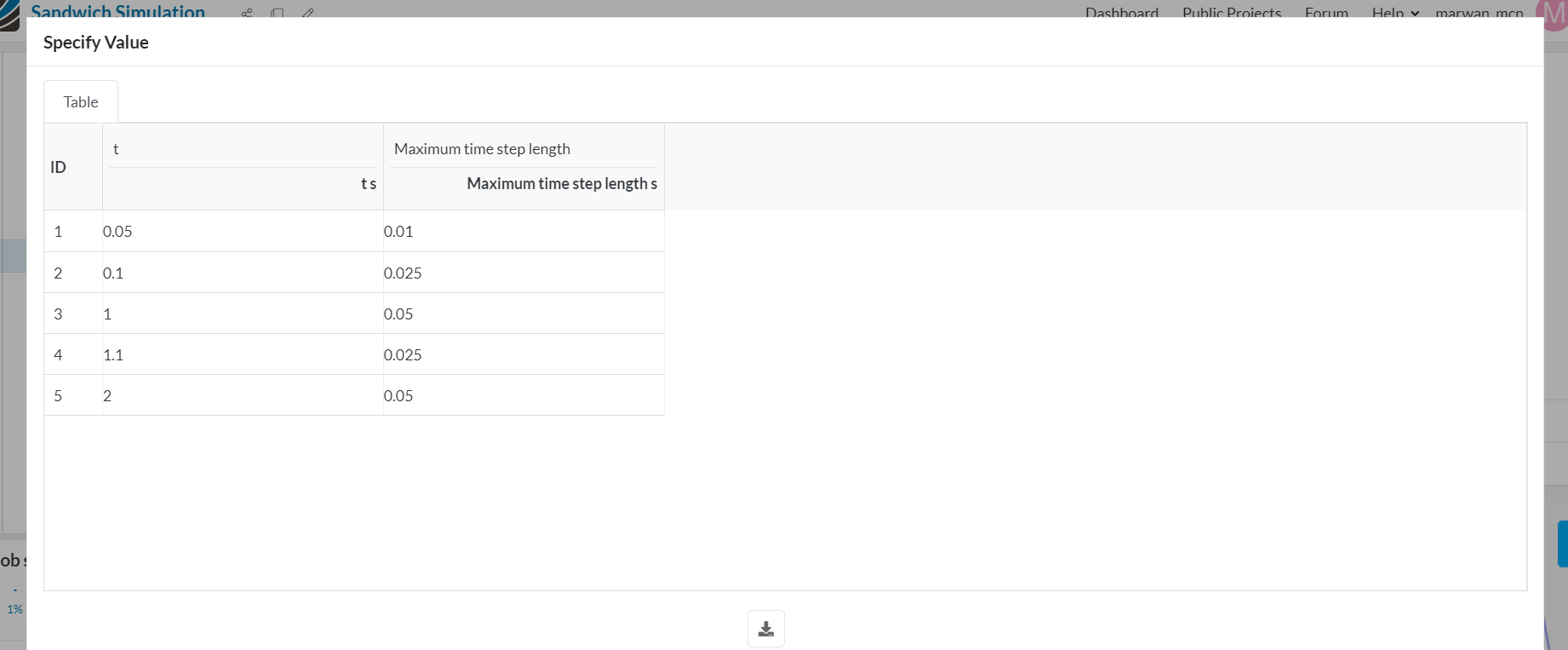
The penetration might be due to a too high displacement of the top plate across time steps. Please reduce the time step to better capture this behavior.
If yes , this was done in hopes of increasing stability of the structure for easier convergence. Does not mimic any real life behavior. I assumed that constraining these faces in x and y direction with z unconstrained would lead to better convergence and it did but support reaction values were 10^-3 times the experimental values.
For the time step suggestion, I have already stepped it (0.01 sec for first few iterations) in a way that it takes 0.015 mm (1 sec is 1.5 mm displacement
Assumption was that leaving these faces free in Z direction would not give much reaction in the Z direction. Shall exclude that boundary condition now.
In the set up, if i change the elastic supports to fix in one direction ( x or y, same as elastic support direction) and taking away the Z free horizontal face boundary condition,
would it be a good approximation ?
Thanks