Bonded contact is a good approach to avoid simulating bolts?

Hi all!

I am carrying out a structural simulation of a multi body structure and I am struggling with the contacts definition. My main problem is that I have several metal components connected to each other by means of bolts, actually, they are 4 parts connected by means of a through hole, as you can see in the figure below.

As I am not interested in simulating the bolts and nuts of the structure I am wondering how I might connect all of the parts together. In a previous simulation where I could use symmetry I only had 2 parts and I connected them as shown below.

I used the Bonded Contact approach applied in the inner cylindrical faces.

1. Was it an acceptable approach taking into account that both master and slave faces are not strictly in contact, except for the common edge they have in contact?

If it was an acceptable approach, my question is:

2. Can I put togheter in a single Bonded Contact constraint the four faces included per each hole shown in the first picture? What aproach would fit into my analysis according to your knowledge?

Besides that, I made some tests trying to “shrink” the number of contact constraints during the pre-process stage by doing the following

I “compacted” all the main contacts in only one constraint. However, the results I got are not the same.

3. I guess it is related to the fact that I am using only one constraint over several surfaces belonging to diffferent solids, Am I right? Is there a limitation to use one constraint over only 2 different solids?

I need some help with this issue since it is my first multi solid structural simulation and I am a little lost with it. I have read all the documentation and searched for some topics related to Bonded Contacts, master and slave faces selection but so far I haven’t found “The answer”.

Many thanks in advance.

Regards,

Alex

Hi Alex (@alexroque) and thank you for reaching out to us!

Let me tag our FE experts and PowerUsers @BenLewis, @cjquijano as well as @ggiraldo here who might give you some good tips on your simulation setup and how you can improve it.

All the best!

Jousef

Thanks @jousefm for the help! :wink:

Hi @alexroque,

Here are my two cents:

Your approach might seem counter intuitive, but looking at the results I think it works, as it keeps the part tied together as bolts would. Local stress around the holes wouldn’t be realistic though, which might be important if you think this is a critical area prone to fail.

The important aspect here is the masters/slaves is consistent and the position tolerance value is small enough so far faces are not connected.

And how did they turn out? Did you notice any difference? Experimenting and comparing different modelling approaches is a very powerful tool!

What differences did you find? Could you point the compared simulations? (I looked your project and there are many) Take into account what I said before when judging this.

Up until this point the issue is not clear to me. What “answer” are you looking for? Do you have a reference solution? In what terms?

Bear in mind that bonded contacts are only modelling tools, and as such they have their advantages and limitations. The final results are also influenced by other modelling decisions, such as material parameters, mesh refinement, load application and restrictions.

2 Likes

Hi @ggiraldo,

Many thanks for sharing your knowledge with me, I really need it!

This is really interesting! Could you please give me more details about it? How would you chose the master/slave faces in my case (4 cylindrical faces not in contact with each other, only between edges)?

I wouldn’t say it is just “a very powerful tool” but “THE TOOL”!:rofl: All joking aside, I agree with you, I experiment as much as I can when developing new kinds of simulations.

I know my project is a little bit of a mess at the moment…:confounded: You know, experimentation, trial after trial and all that… My fault! I will clean it up a little when I finish with it. However, if you want to look for the differences you can compare the simulation named Static_frame_analysis_multicontact_2_mesh-improved (the one in the middle), which has several runs but all of them have 14 contacts defined, whereas the following simulation (Copy_of_Static_frame_analysis_multicontact_2_mesh-improved) only has 6 contacts. I’m sorry for not posting links, I’m at home now with a tablet, tomorrow morning I will be able to answer better.

I mean an answer to a good way to model a contact between bolted parts avoiding the use of the bolts themselves. I don’t have any reference, that’s why I’m asking, because maybe someone has struggled with a similar case to mine in the past and knows how to model this kind of contact.

Again, thanks to spend some time to help me!

Regards,

Alex

Hi @alexroque

Read this document, it might give you more ideas about the bonded contacts.

About the modelling of bolts using this method, I think that although it is capable of tying the bodies in a similar way, the lack of accuracy for the local stresses might represent a problem. It comes down to your area if interest, but then, if you don’t care about this phenomena, why not to model each body separately?

You also don’t need to fully model the bolt to take into account its effects. A simplified mode, like a cylinder with physical contacts and pre-stress might yield good results. Take a look at this or this example.

Hi @ggiraldo,

Many thanks for your valuable help! I have to say that I already checked your case about bolted connections yesterday when I realised you were looking to my project :grin: It is very interesting and it gave some idea.

What do you mean by model each body separately? Do you mean to use Bonded Contact for all the holes between 2 bodies in contact instead of trying to model all holes belonging to more than 2 bodies?

I am really grateful for providing such an interesting case! Some days ago I was trying to find a case were I could find some inspiration with no luck and the crane case you provided did the trick! However, I have some doubts about it since there are some Bonded Contacts between bodies that are not really in contact that I don’t really understand. Below you can find a figure that shows it.

Do you know why Ben Lewis (@BenLewis ) used this kind of modeling? Why did he use bonded Contact between separated solids?

Thanks for everything!

1 Like

Hi Alex (@alexroque),

in the gantry crane simulation I used rubber elements to stabilize the model. The rubber is soft enough that it doesn’t change the results in any significant way but hard enough to stabilize the pins. The pins and bushes are constrained with separating contacted but the whole joint is stabilized with bonded contacts via the rubber elements.

This is a technique I have used many times with a lot of success. However, it is not what I would recommend in your application. In this case, where you do not want to model the bolts, I would used bonded contacts between adjacent parts. To do this you will need to split the faces of parts that are touching each other. The face should be split with a circle the size of an appropriate washer around each hole. This will result in doughnut shaped areas around each hole that are bonded to their neighbors. This is a simplification that approximates the physical reality pretty well but will still result in some artificially high stress around the holes.

Sorry I did not jump in earlier. I saw your post and wanted to respond but I’m too busy at the moment to create an example project for you. I hope this helps.

Regards, Ben

4 Likes

Hi @alexroque,

I mean literally simulate every single part separately, not the assembly. Then you wouldn’t need bonded contacts.

Thank you very much @ggiraldo and @BenLewis ! Your help is really valuable, especially your explanation @BenLewis. However, I still have some doubts on your rubber approach. I’ve been studying it deeper lately now I have your information in order to use it my studies, maybe I use something similar in my frame analysis. Below you can see my approach, I try to avoid using physical contacts since I would like to keep it linear and easy to simulate, since this is my first multi body analysis.

Pin and rubber approach

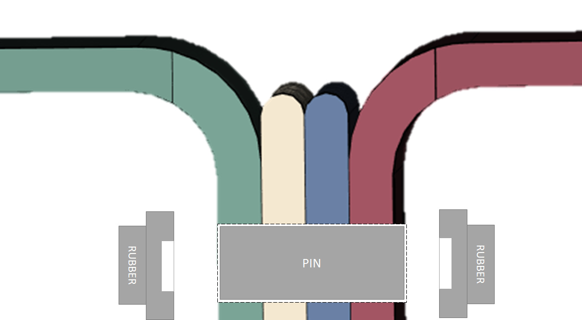
Contact specification
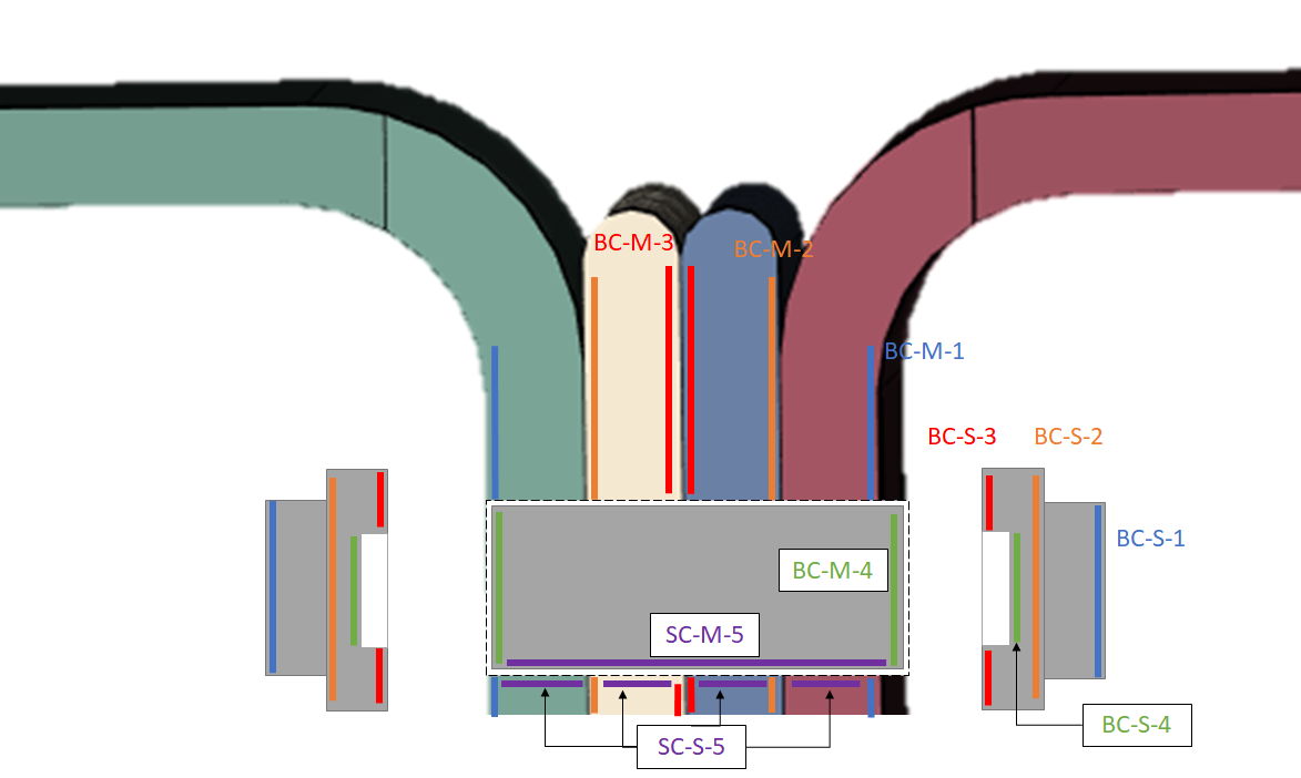
Contact Code:

  1. BC-X-X: Bonded Contact;
    SC-X-X: Sliding Contact
  2. XX-M/S-XX: Master/Slave
  3. XX-X-Y: Yth contact

If I understood well your Crane case, my approach would be more or less similar to yours since I only replaced your physical contact between the pin and the inner hole faces by a sliding contact. What do you think about it? Would it work?

Besides that, as I already mentioned, I still have some doubts on your implementation of the contacts in your case, let’s see a figure,

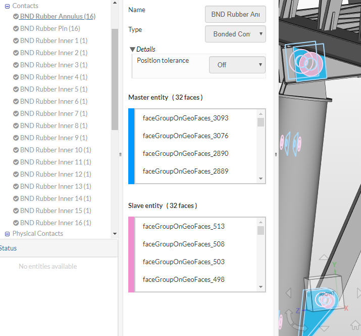
When you define the contacts between the outermost faces of all the junctions and the rubber elements (BND Rubber Annulus) you do it in a single contact constraint. And you do the same process for the planar faces of the pins and the rubbers (BND Rubber Pin). However, when you define the artificial contact between the rubber parts and the faces of the inner part of the junction you do it one by one, beeing each one in a single contact constraint (BND Rubber Inner). What is the reason for doing so?

Regarding your suggestion

What do you think about my initial approach which I think is similar to what you suggest? Below you can find a quote of my own

Would you recomend this use of Bonded Contact constraint for the bolts? Or would your approach be better? I guess I already know your answer…:sweat_smile: However, I would like to know your opinion about my approach.

Don’t worry, I understand you are a busy man. I don’t mind waiting for an answer if it as good as yours has been! :wink:

Regards,
Alex

2 Likes

Hi Alex (@alexroque), you have some good questions for me. This is a complex topic but I will do my best to give you a good explanation.

I agree. I often start with a linear analysis even if I intend to progress to a non-linear analysis later. Or put another way, I always start simple and only add complexity as needed.

I’m not sure I agree with your proposed approach but this may be because I don’t understand your application. The approach I used in the gantry crane project was for pins where it is important that the joint cannot carry a moment. In your case you are using multiple bolts over a single face where the intention is to prevent rotation. By using the “gantry crane” approach you are adding a lot of complexity but I don’t see the benefit.

By replacing the separating contact with a sliding contact the load on the pin will be carried over the entire circumference of the pin instead of over just the half of the pin that is in contact with the hole. However in the case of a bolted connection the pre-load in the bolt should clamp the joint so that it is the friction between the plates that prevents one plate sliding over the other. In this case the bolt does not carry any shear (unless there is insufficient pre-load or insufficient friction to prevent slip).

In Code_Aster when you define a surface as master it actually treats the entire volume as a master. Any slave surface will be bonded to the nearest master surface (even if it is a different surface used in the definition). In the case of the gantry crane project I was not able to combine all “BND Rubber Inner” definitions into one because this would result in some slave faces attaching to the wrong master face. For example, there would be a problem when combing “BND Rubber Inner 13” and “BND Rubber Inner 15”. The master surface defined in “BND Rubber Inner 13” makes the entire column a master volume. When the slave surface defined in “BND Rubber Inner 15” tries to bond with it’s nearest master surface it finds the outer clevis of the joint and not the intended inner surface. This problem is solved by defining each bonded contact separately.

Yes, I like this approach. However, I would do it slightly differently, with washer shaped faces (as explained earlier).

I recommend you try the following techniques (in this order):

  • Bonded contact (with washer shaped adjacent faces).
  • Model bolts and bond all faces (washer shaped) between bolt and nut
  • As above but with bolt preload
  • As above but with separating contacts (similar to this project)

The first three techniques are only valid if there is no slip or separation of the joint. Probably the this first technique will be enough.

3 Likes

Hi Ben (@BenLewis ), I’m sorry for not responding to your extrememly helpful comment, I have been busy finishing my FEM simulations and doing a report with the results and now I am simulating another device (CFD and FEM).

Finally I only used your first approach but in my way, I mean by joining together the inner cylindrical faces of the holes.

I really appreciate all information you provided, actually, I spent a whole afternoon of a day off I had reading the links about the bolted connections you have in your case and I end up with the feeling that that afternoon had been more useful than my whole degree in mechanical engineering :rofl:

This is very interesting and I would like to get into it deeper if I have some time but, at the moment I’m forced to jump out to another simulation and leave this aside.

I’ve been looking for this explanation for several days! Thanks a lot Ben, that’s what I wanted to know about contacts and master/slave faces selection! Isn’t it a little weird that the programs treats the whole body as a master entity instead of only the faces you select? What’s the point in doing so?

Again, Thankyou Ben for your valuable information it really helps a lot!

Regards,

Alex

I agree. It is not intuitive and I can’t think of any good reason for doing this. @rszoeke might be able to explain the reason for this behavior.

You’re most welcome. I’m glad I could help out. Thanks for the positive feedback!

3 Likes