Hy Guys,
I study at Budapest University of technology and economics
My thesis theme is BMW DOHC valve control stabilisation. And I make a few simulation the example of @rszoeke workshop Analysis of valve spring assembly, and I made simulation at 3000RPM, 4250RPM, 4500RPM, 5000RPM these simulation finished with good results
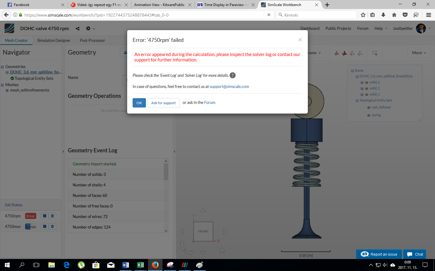
And final i would like to make a simulation where the camshaft is rotating 4750RPM with the same numerics and simulation setup as the other finished simulations but I don’t know why it is always run to error. It is not show anything, just error. I tried it with PETSC and MUMPS equation solver, but the result was same.
Very interesting project you have here! We will have a look at your project and come back to you asap! Hope that’s fine - keeping you up-to-date in any case.
Hi @zsoltpeitler,
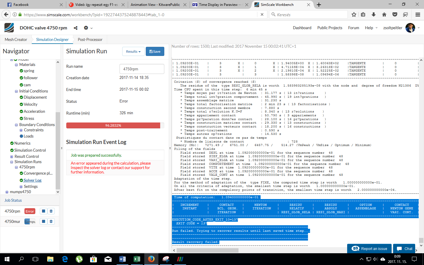
it looks like this was a memory problem at the end of the simulation. I increased the machine size and restarted it. Once it finished I will inform you if it worked.
You can also follow the run progress here: SimScale
Thank you very much guys you are the best
What was the problem because i tried increase the number of cores but the result was the same for me (error)?
Hi @zsoltpeitler,
as the name “32/4” indicates I sued a 32-core instance but only 4 parallel MPI threads (each will then use 8 shared memory parallel threads). This has several implications, one being that each MPI thread has a larger portion of RAM available (4 times more than the default 32/16 setting), which solved the problem.
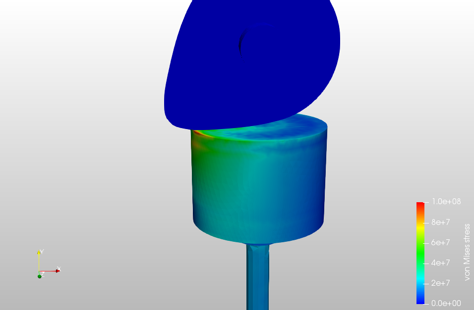
Regarding the floating valve, the result are very representative.
But when i post process the results. I realized that i have a little problem with my physical contact of my cam and follower. While the camshaft pushing the hidraulic follower only in the follower awaken stress. I can’t detect stress in the camshaft. What’s worng with it ? @rszoeke do you have any idea for it ?
Hi @zsoltpeitler,
as you are prescribing the cam movement with a “rotating motion” on the whole cam volume, this part becomes rigid and no stresses are calculated. You would need to only prescribe the rotation of the cam shaft faces to also see the stresses in the cam.
As suggested by @rszoeke that applying only rotation to the surface will solve this problem. But keep this thing in focus that a physical contact between two deforming surfaces is much harder to perform compared to one as rigid. I would like to suggest you two things in this case:
Not related exactly to this problem but try to rotate your camshaft such that it is already in a position where it is just going to hit the follower. In this way you wouldn’t have to wait for the camshaft to hit the follower for long thus will save considerable simulation time. In this case you have to re-upload the CAD, duplicate your existing mesh and give a new CAD to it. Reassign entities and create a new mesh. Do the same for Simulation Setup.
Once you have applied rotation only to the faces, give the penalty stiffness of more than 12k, make it 13 or 14k to resist as much penetration as possible. You can also try Augmented Lagrange but it is mostly unstable but if it works, it is way faster than penalty.