PROJECT LINK:
INTRODUCTION:
The Blended Wing Body shape allows unique interior designs. Cargo can be loaded or passengers can board from the front or rear of the aircraft. But this kind of the wing used in military aircraft only. So, this project is about the flow visualization of the aircraft with blended wing body which provide diagnostic information about the flow around the Aircraft.
GEOMETRIC:
The Blended Wing Body Aircraft been made with all the Designing Parameters in SolidWorks as shown in Fig.1 below.
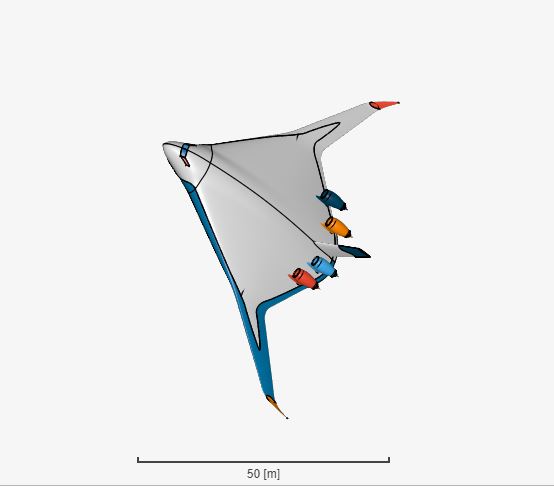
Fig.1: CAD Model of the Blended Wing Body Aircraft
SIMULATION SETUP:
For the Project compressible flow simulation type has been chosen because this type of aircraft moves at high Mach Number. Along with the K-omega SST turbulence Model which tells about the turbulence energy and scale. and the steady state is chosen as time dependency because this kind of simulation is been done under ISA (International Standard Atmosphere) So the values does not change with time.
MESHING:
Meshing is an important part of any kind of simulation. Hex-dominant is used as the algorithm of the Mesh. Along with the External meshing mode. As the accuracy of the result is depend on the Fineness of the Meshing.So, here Mesh Refinement is also used at the edges of Aircraft and Moderate Mesh is been used as the fineness of the Meshing with 16 number of processor. For external meshing mode two Geometric Primitives been used inner and outer box around the aircraft as shown in the Fig.2 & Fig.3 below.
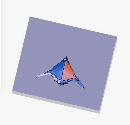
Fig.2: Inner Mesh Box around the Aircraft
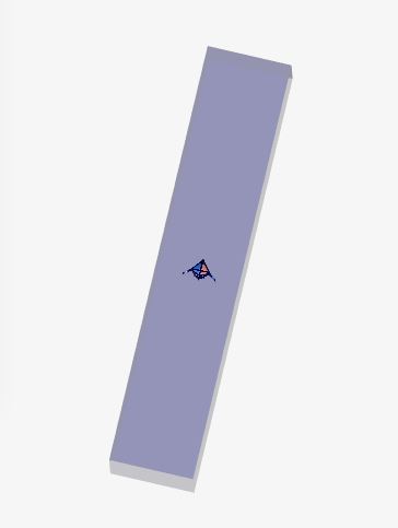
Fig.3: Outer Mesh Box around the Aircraft
After a Mesh operation of around 18 minutes here we got 1.3 M cells and 1.7 M nodes for this Meshed Blended Wing Body Aircraft as shown in Fig.4 below.
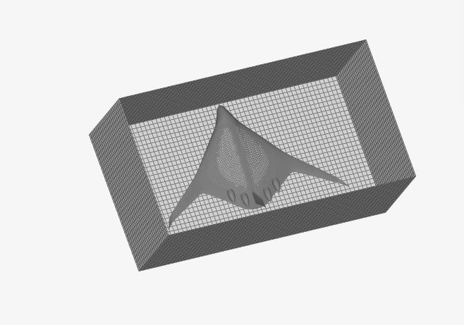
Fig.4: Meshed Blended Wing Body Aircraft
MATERIAL:
For this simulation AIR material is used from the material library of the SimScale. Air is applied over the complete volume of the aircraft as shown in Fig.5 below.
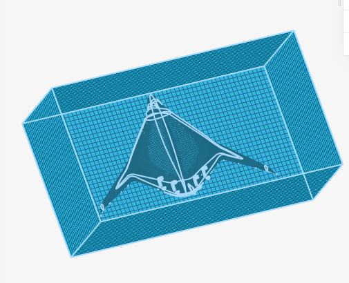
Fig.5: AIR applied over the complete volume of the aircraft
INITIAL CONDITIONS:
Initial conditions velocity for this simulation is given 500 m/s in Z-Direction.
BOUNDARY CONDITIONS:
For this simulation total five number of the boundary conditions been used
- Velocity Inlet: velocity is applied at the inlet of the body with 500 m/s in positive Z direction as shown in the Fig.6 below.
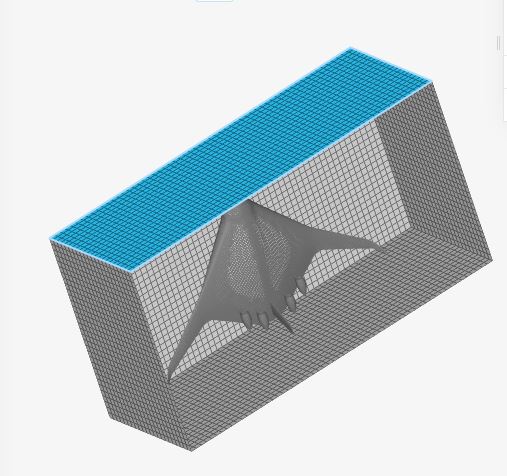
Fig.6: Applied Inlet Velocity Boundary Condition on the aircraft
- Pressure Outlet: Pressure is applied at the outlet of the aircraft body as shown in Fig.7 below
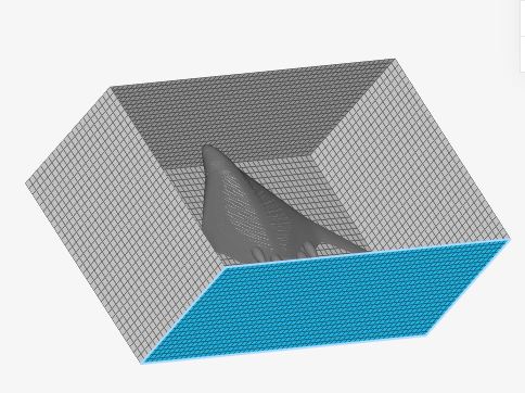
Fig.7: Applied Pressure outlet Boundary Conditions on the aircraft
Walls: The whole aircraft body along with the Geometric Primitives has been chosen as wall instead of inlet and outlet side of Geometric Primitives as shown in Fig.8 below

Fig.8: Walls Boundary Condition on the Aircraft
SIMULATION RUNS:
After completing the simulation setup simulation run 1 has been started which took around 184 minutes of time to get done and we got the Following result as shown in the Figure below.
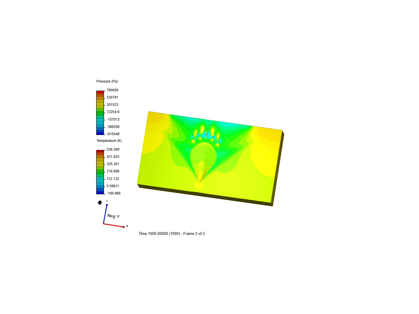
Fig.9: Pressure changes at aircraft surface.
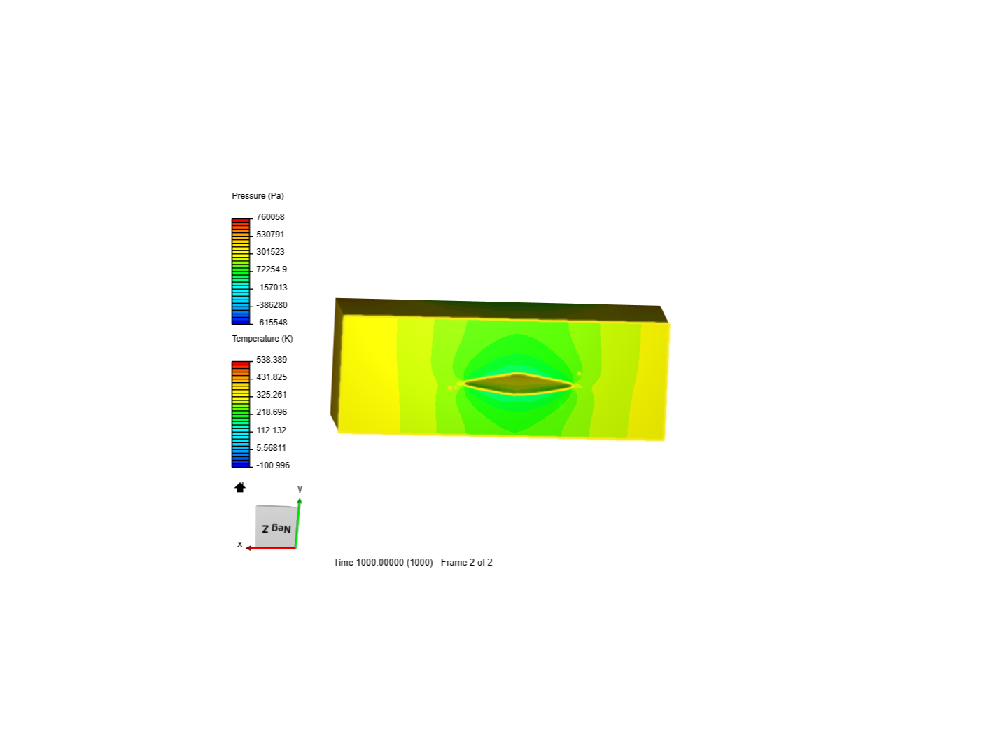
Fig.10: Pressure SIde view on the airfoil.
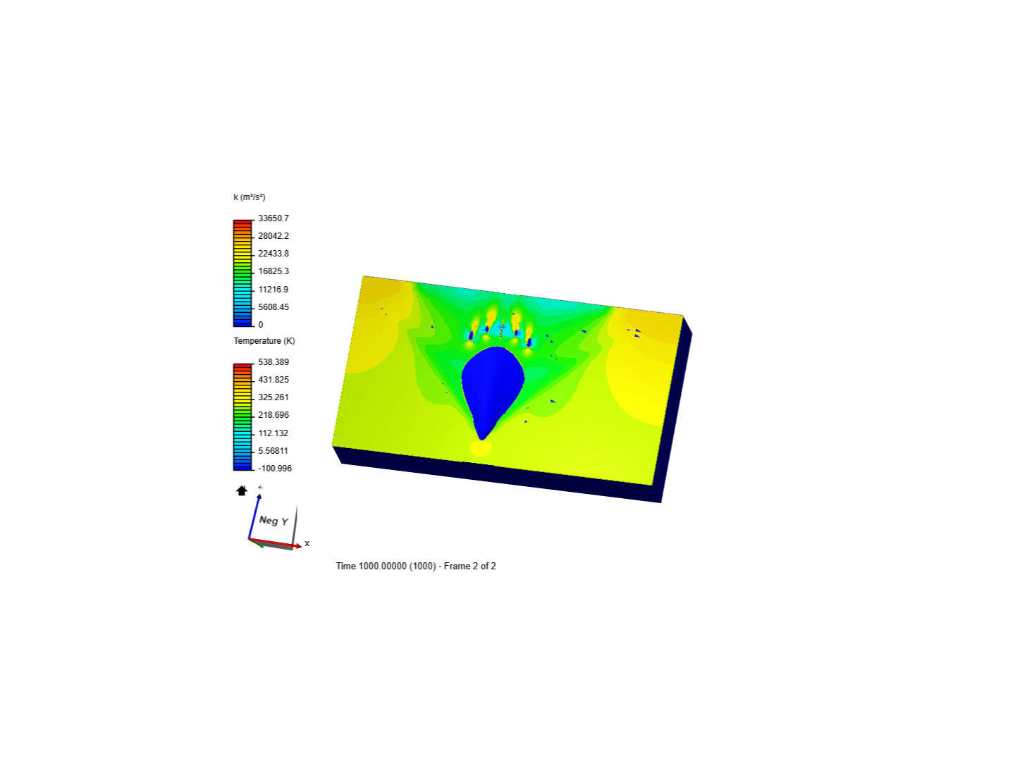
Fig.11: Energy of the Turbulence Produced during analysis
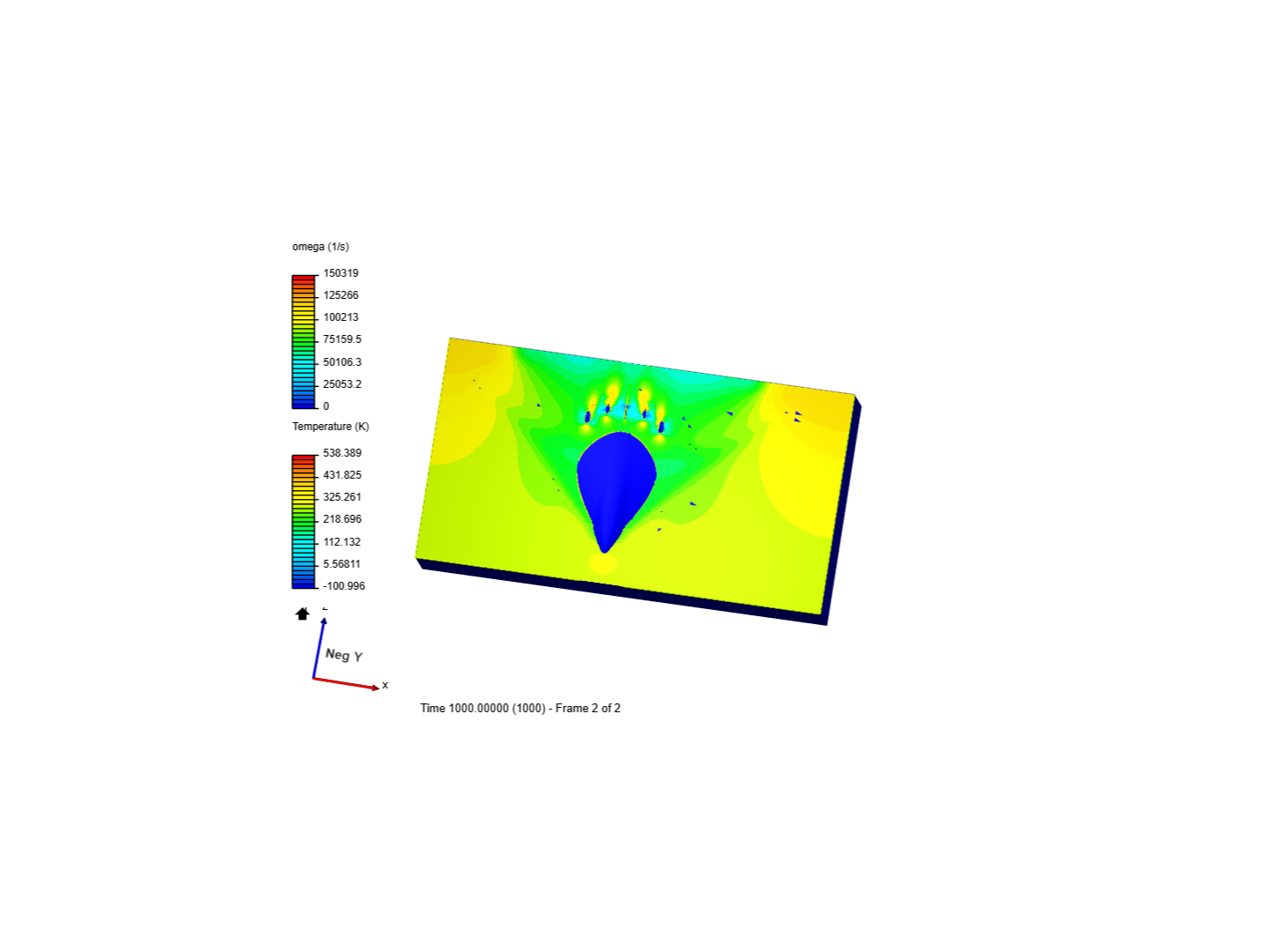
Fig.12: Scaling of the Turbulence
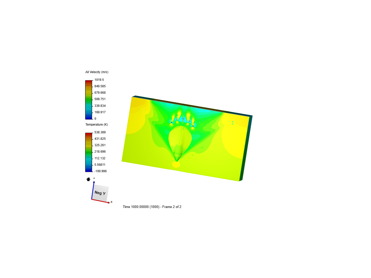
Fig.13; Velocity of the Fluid Flow
CONCLUSION:
From all of the simulation result we can easily Visualize the Fluid Flow around the Aircraft which can help us in design optimization of the Blended Wing Body Aircraft.
Thank you:slightly_smiling_face:
Deepak