Hi!
Here are the rules for constructing MRF rotating zones:
- There should be 2 volumes in the geometry: a flow region, and a MRF rotating zone
- In your case , the MRF rotating zone would be a simple cylinder (a plain cylinder extrusion with 3 faces, fully solid, fully interfering with the flow region)
- The solid blades should not be in the CAD model - they will cause multi-region mesh errors
Currently, the geometry consists of:
- An incomplete flow region (there is a void in the middle of the domain):
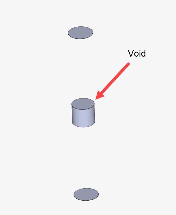
-
In the geometry, “solid2” represents the solid blades, which is not correct. The blades should not be in the geometry - only the negative representation of them
-
There is no MRF rotating zone volume
The most simple way for you to fix this in CAD would be:
- Make a brand new flow region, with a simple extrusion of a cylinder (i.e. a 3 faces cylinder)
- Run a boolean/combine operation, to remove “solid2” from the newly created flow region. This will create a negative representation of the blades
- Construct a MRF zone as a simple, 3-faces-cylinder
- Delete the “solid1” from the geometry
At this point you should have the 2 necessary volumes only: a flow region, and a rotating zone.
Cheers