I want to make a simple FEA on a shaft which is loaded by it’s own weight and some remote force which generate torque. The torque is then counter-balanced with the keyhole’s wall. So I expect the highest load on that wall.
I tried two methods for modeling bearing support:
Fixed
Rotating motion
The Fixed constraint is not so good since it doesn’t allow the shaft to rotate the key is not even loaded.
The Rotating motion constraint seems the good one for me but the terms like base point, rotation axis and rotation angle are not fully clear for me. And the results are also quite nonsense.
May you please have a look on it and help me to find out what to do?
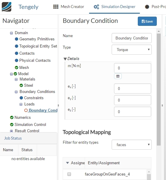
concerning the boundary condition “torque” that you want to apply there is an easier way to apply torques if you switch to “Static Analysis” instead of “Static Analysis - advanced”, you are able to apply torques directly at the desired component if that is more convenient for you.
The “remote point” as well as the “rotation axis” and “rotation angle” are explained in the documentation: Remote Force & Rotating motion
I also saw that you applied another fixed constraint at the side of the “keyhole”. Do you want to bend the shaft or apply torque at those faces? Just to be at one with you.
But if I load it with torque then I’m wondering wether it applies on the shaft as shear load as well? Probably the shear effect is not that critica in this casel but I’m not sure…
Thank you for the documentations I’ll check them. So do you also think rotating motion is the way to model bearing support?
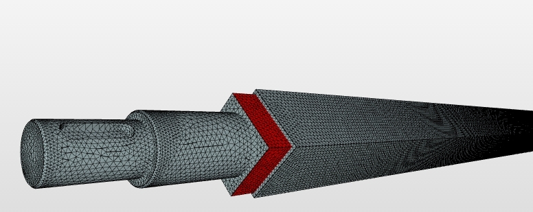
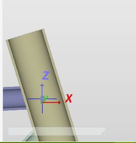
The case is:
The shaft is supported via bearings.A remote force acts at the red marked surfaces causing torque and shear. The torque is balanced with a motor so that is represented by the keyhole’s fixed wall. That prevents the shaft to turn.
if you are not sure then just give it a try. You can run different scenarios and trade off one solution against the others and which one makes more sense.
If your bearings are allowed to rotate around let’s say the z-axis simply “lock” all displacements and rotations in the other directions except the rotation around the z-axis. Does that make sense to you?
Now it is a bit easier to grasp what you want to do. Well, if the counterforce really acts on the inner side of the keyhole then you could lock all rotations contrary to the rotation of the shaft. If your model also allows the simplification of “holding the part of the shaft where the key is” you can select the surface and apply the boundary conditions at this particular surface.
If my explanation was entirely ambiguous, just let me know. We’ll make it work.
I made a copy of your project and you can find it here.
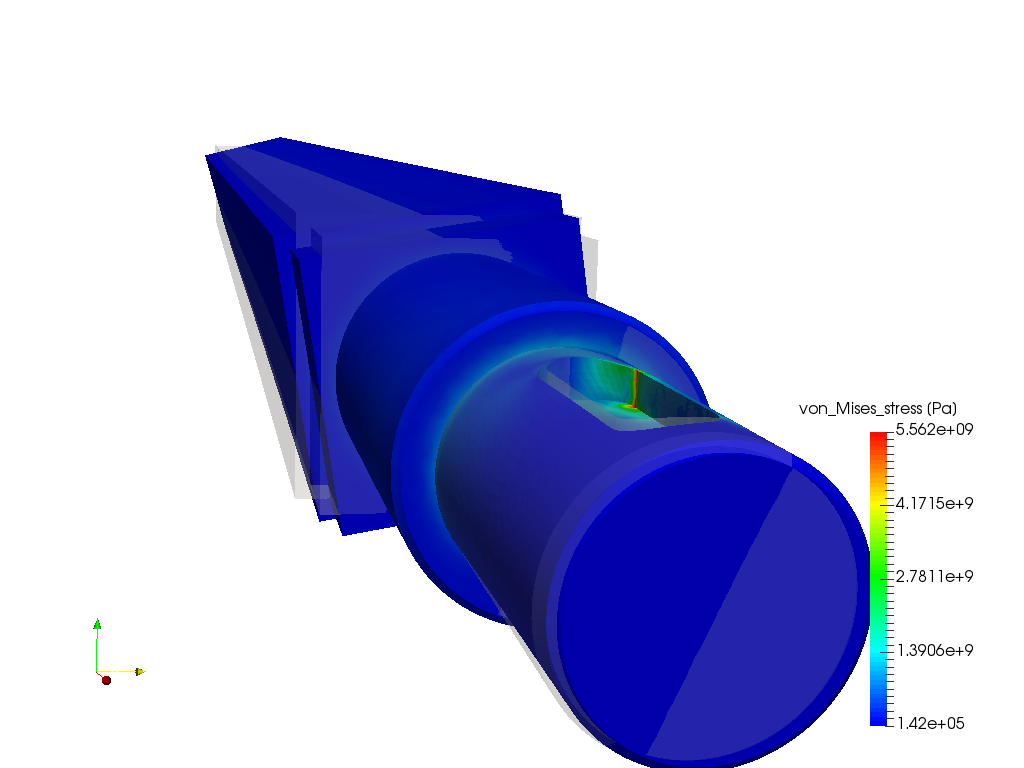
What I did was create a Remote Displacement boundary condition for each bearing (2X). The one away from the key is constrained in all directions except rotation about X. The bearing near the key was constrained in all directions except X rotation and axially in X. The wall of the key was constrained in the Y direction. On the flat face furthest from the key I applied a Remote Force of 1000 Nm about the X axis.
This should simulate the twisting of the shaft due to an applied torque pretty well. In the project I also did a course mesh which solved in less than a minute. The fine mesh was taking about 15 minutes. You could look at doing a course mesh with local refinements around the key slot.
I hope this help. lease let us know if you have any more questions.
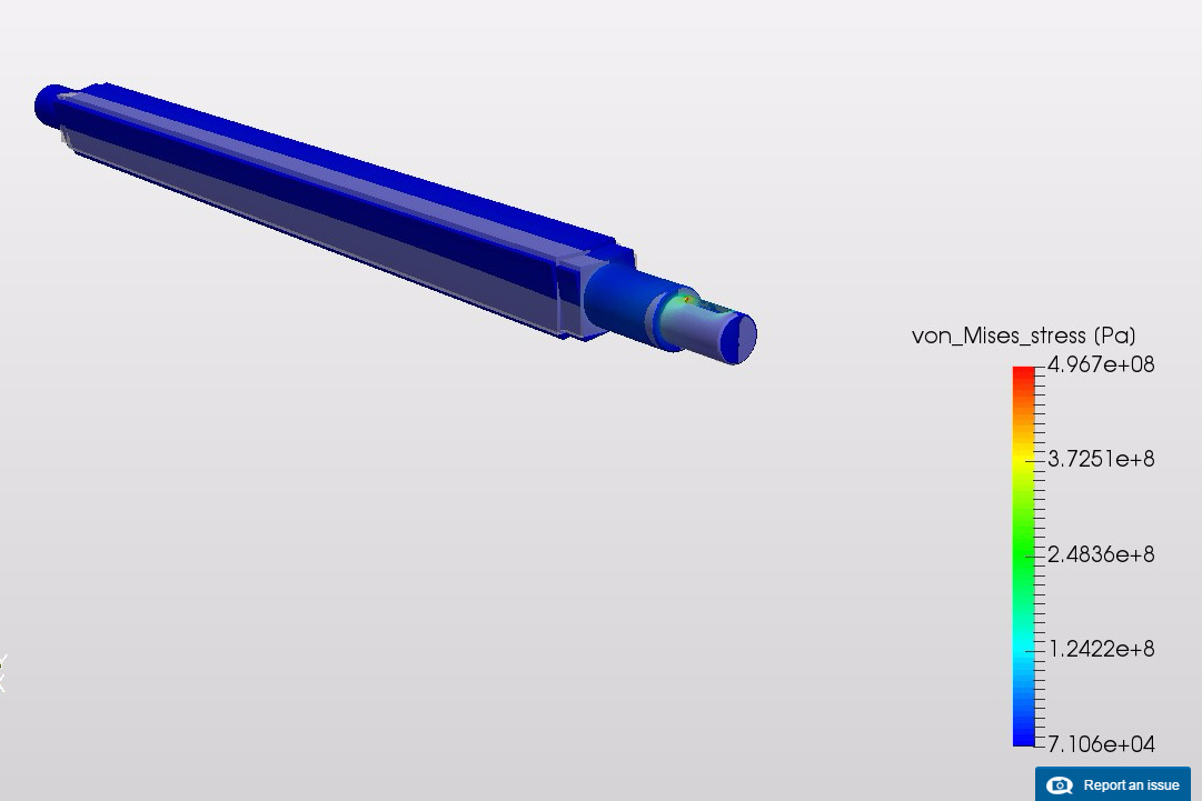
I’ll check your sim session. The result looks what I expect so it should be OK. I’ll compare the stresses with the hand calculations and will tell the result here. I’m really curious!
I find it really nice how the two simulations coincide! The sad thing is that >490 MPa stress is a bit too much for a normal steel shaft especially under alternating loads. The stress concentration at the key hole is quite massive I need to re-design the part.
hi @jousefm
thanks, by using geometric primitive option I got to know where my origin is. secondly, I can even create points over there.
I have a question, is it possible to show the distance from the origin to an entity selected? if yes, It would be easier to create points and assign them to remote ones.
another question, can we assign the primitive point as remote?
the last one, when I create a remote point am I creating a local coordinate system?
You can create a point at the Geometry Primitives to see if the point you are using is correct - it cannot be assigned as a remote directly but has to be defined explicitly. It is not yet possible to show the distance. This could be done in the CAD program of your choice.
Regarding the coordinate system: Everything is related to the global Mesh coordinates and directions!
And rotations can be allowed using a remote displacement as a constraint choosing the corresponding axis.