Introduction
This post is aimed at users of SimScale that are not engineers or aerodynamicists and with little technical knowledge; instead, they know about designing buildings, sites and urban areas. In the post, we want to show users how they can understand results but also use results to improve their design. SimScale makes it very easy to perform wind studies, but naturally, the user needs some fundamentals to understand impacts and make suggestions for improvement.
The electrical circuit analogy
Fluids can be very complex and very hard for us to understand. In contrast, we tend to find electrical circuits relatively easy because many of us are taught about it, at least to the level we need for this discussion, as early as a primary school level. Therefore, we draw an analogy to electrical circuits when explaining fluid flows. Let’s take this term by term.
Voltage = Pressure
Voltage, sometimes known as potential difference, is a ‘force’ that pushes electrons through a circuit. This is similar to pressure, where a high-pressure difference will move air from high to low pressure.
Current = Flow rate
Current is the number of electrons being pushed through a circuit; if there is a high force (voltage) and a low resistance, more current is naturally pushed around a circuit. Similarly, if there is little airflow resistance and a high-pressure difference, there will be a higher flow rate.
Resistance = Resistance
As you would imagine, the electrical resistance is almost like a blockage to the current, i.e. a light bulb provides resistance in a simple circuit; the higher the resistance, the lower the current. In basic air flows, resistance could be a collection of buildings, trees or other things that block the flow. These would all limit the amount of flow going through the obstructed path.
Bringing the analogy together
You may remember this formula from school:
I=V/R
where V is voltage, I is current or flow and R is resistance
You may also remember that this is also known as Ohm’s law. However, that is not so relevant here. What is important is that we see the relationship, flow increases as voltage increases and/or resistance decreases. I bet now I have written that you now completely understand how this is relevant. I joke. Let’s take a more practical look at why this is relevant to Building Aerodynamics and urban design.
A basic example
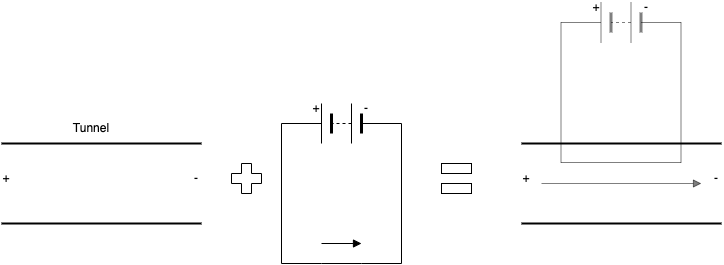
Let’s start with a straightforward scenario. If I had a tunnel, with a pressure difference across it, with high pressure to the left. The circuit diagram would look like this:
If I said, with the same setup, let’s plant a tree in the tunnel (ignore the obvious problem here). The circuit would look like this:
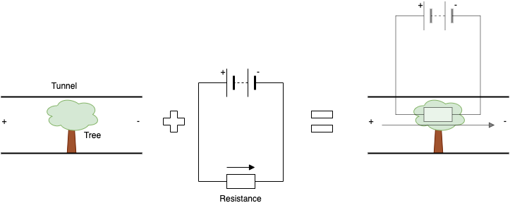
Now, if I was to pose a question like, which setup would have a higher wind going through the tunnel? You would answer the empty wind tunnel, as there are no restrictions, or to put it another way, less resistance. Note how we expect the flow to go from left to right, high pressure to low pressure. Hopefully, you can see how this analogy helps us understand flow paths.
A more realistic example
Although I might have proved my point about the circuit diagrams, you might be thinking, how useful is this? We knew intuitively which scenario flow would be more or less. Let’s increase the complexity to see how we can use this logic in a less obvious scenario.
Let’s consider that the same tree is not placed in a tunnel. It’s more realistically put in an open atmosphere. If we don’t overthink this, we can use the same analogy to determine what flow might do by introducing a parallel circuit to the resistor.
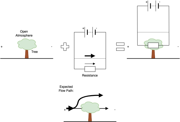
If we look at the expected flow, we were able to determine that flow might go over the tree whilst only some go through it. This is because, like electrical flow, air will follow the path of least resistance.
I said, ‘if we don’t overthink it,’ why did I say that? First, trees and flow are 3D, so if this were a tree in isolation, the flow would go around it as much as it goes over it. Secondly, this could be as complex as we want, but that’s why we have CFD. Let CFD do the hard work. Let us use this method to make good intuitive decisions.
Other helpful electrical circuit analogies
As we develop this article, we may add additional sections to assist with commonly asked questions. There will also be a follow-up article with typical flow effects, like cornering and channelling, and how we can mitigate using the circuit analogy.
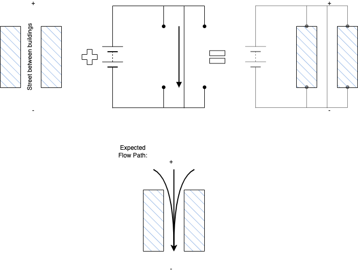
Circuit Breaks
A more prominent use of the analogy, but worthy of mentioning, is a circuit break. In fluid flow, this can be any solid object, such as buildings. Below is an example of channelling.