Hello guys
I want to create sealed IP67 box for automotive electronic unit. This box has to be sealed by compresion of rubber gasket and has to endure “hot” test of 5J from 20 cmm(hit by hummer 1.7 kg)
I need an information how many screw connections are required to compress the gasket(what should be the minimal distance between them?)
https://www.simscale.com/workbench?publiclink=77387d2d-1e2a-4381-b302-7f954ab6c544
Hey @mydlikowskij!
Looks like an interesting case. I managed to have a look at your model. What I have understood so far from your question is that you need an optimal solution for proper sealing of your electronic unit. For this you have to perform an initial simulation case according to which you can decide further.
I can also see that bolts/screws are missing from your simulation. Without them it would be difficult to define prestressing in order to compress the sealing. I would try to run a simple case for you and get back to you soon.
Best,
Ahmed
Hey @mydlikowskij!
Thanks a lot for your patience. So I have managed to perform two simple cases for your gasket assembly. Since your model was symmetric, I took only quarter of it in order to perform the simulation in lesser time. I added the bolts and only applied a prestressing via fictitious clearance in order to have the over tightening effect of them.
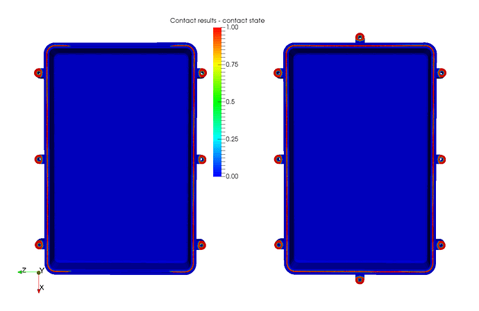
The original case from you resulted in missing regions where the contact is not developed properly resulting in leaked spots. In order to solve this problem, I added two more bolts on the top and bottom side of the cases which resulted in a proper sealing. It seems like this configuration is good enough to seal the gasket. But of course you can make further modifications to it in order to make it even better. You can find the created project here: SimScale
Below are the results of two case: original case on left, modified case on right.
I hope this helps you in solving your problem. If you have any question/s, feel free to ask.
Best,
Ahmed
4 Likes
Hello Ahmed
thank you for your comments and work you did regarding my problem.
Can you elaborate a little bit more what conditions did you take to perform this analisys?
As I understand you manage this problem by establishing “contact” analisys?
In addition
Second important thing to is to calculate the force required to apply on screws, to finally ensure tight and hermetic sealing.
Hey @mydlikowskij!
I have considered a nonlinear analysis due to the fact that physical contacts will be involved. Having physical contacts allow me to add fictitious clearance which gives the same effect as the bolt has been tightened. I also considered some frictional effect, more with sealing and less between casing and bolts. The symmetry boundary conditions were also applied due to symmetric model taken in to consideration.
Yes, physical contacts were required here due to fictitious clearance.
Of course this thing you can do in this case also. You just need to output the forces on either the bolt or case contacting face. This will give you the force required to compress the sealing that much.
I hope I answered the questions. If not, please feel free to ask again.
Best,
Ahmed
I will try to redo the analisys step by step on my own with the use of contacts to learn how to make it right
how can I output the forces on bolts?
Under ‘Result Control’, click ‘New’ next to ‘Area calculation’ in order to create a new area calculation method. Rename it if you like, then select ‘sum’ next to type, ‘force’ next to field selection and then ‘nodal force’ next to component selection. Select the face from the viewer you want to have calculated nodal forces on, click ‘Add selection from viewer’ in order to select the face. Click ‘Save’ to register changes. Start a new run and when finished you would be able to see an additional graph for nodal forces.
1 Like
Ahmed
can you lead me step by step through the process you followed to prepare the simulation?
First - how can I prepare symmetry of geoemtry? Did you make it out of simscale environment or it is possible inside?
The symmetry of the geometry was done using Onshape. Unfortunately you can’t do these geometrical operations on SimScale. But forexample on Onshape you can upload the geometry and cut it along the two perpendicular planes via split part operation.
plus for Onshape to make such changes on models possible for free:)
ok, when models in onshape wre cut, have you assigned the symmetry of goemtry somehow in simscale, or not?
Yes the symmetry boundary condition will be applied while setting up the simulation. This you can also see in the shared project.
ahmed
how did you set the conditions of your simulation? what is the driven factor of your results?
The only driven factor of my results was the prestressing of the bolts via fictitious clearance. Other than that bonded contacts were used for considering the contact of sealing and bolts with lower casing. Other than symmetry, the lower case was also fixed using nodal restriction. This was all I have done in this case.

