I am going to be doing a project in the future where a seal has broken and I need to find out what caused the failure. In order to simulate this I need to apply the given clamping force onto the holes of the seal. Is there a way to do this without setting it as a fixed support and instead I can give the value that it can clamp before the bolt would break off? As always any help is appreciated.
Hi @tsloan,
Check out the Drone Design Workshop, Section 2, and it will walk you through setting up bolts with a preload. You can start watching around the 25 minute mark.
In general, in Simscale the preload is defined by adding a fictitious clearance between the contact pair. Take a look at this and let us know if you have any more questions.
Good Luck,
Christopher
2 Likes
Hi @tsloan,
When performing a simulation with bolt preload it is often useful to visualize the difference in stress from one time step to another. If there is sufficient preload there should be no change in stress in the bolt.
You can find a Paraview programmable filter to assist with this task at the link below. There is also an example project to get you started.
[!!!THIS LINK IS NO LONGER AVAILABLE!!!]
I hope this helps.
Regards, Ben
2 Likes
Hi @BenLewis,
I looked through your example and it was extremely helpful. If I know the clamp force provided by the bolt is there a way to apply that without modeling the bolt and inserting it into the design?
Edit: I put the bolts in but for some reason why I try to specify the preload in the bolt it won’t let me select the bolt geometry.
Thank you,
Tyler Sloan
Hi @tsloan,
Currently SimScale does not have virtual elements like bolts, beams and springs. These elements must be modeled in 3D.
I’ll take a look at your project and get back to you.
Regards, Ben
SimScale support (@AnnaFless),
I’ve made a copy of Tyler’s project. I would like to make some modifications to the geometry but the download option is not available. Why is the download prohibited? Here is the project.
@tsloan : can you please send me the original step file? I will PM you my email address.
Regards, Ben
Hi @BenLewis ,
downloading of the geometries is currently being temporarily disabled for certain types of geometries.
It will be back with the next release on Wednesday.
Best,
Richard
Hi @tsloan,
Here is a link to my copy of your project. Please take a look at simulation BrokenSeal01.
[!!!THIS LINK IS NO LONGER AVAILABLE!!!]
I’ve made quite a few changes. Here are the main points:
-
Quarter symmetry to reduce the size of the model.
-
Merged nuts and bolts to eliminate the need for bonded contacts.
-
Added a physical contact between the connecting ring and seal ring to prevent the two bodies from penetrating one another.
-
Added a constraint in the y-direction to fix the model in space. You will need to change this to suit how the body is constrained in real life. I just made a guess at how I thought it might be.
-
Changed the time step definition from auto to manual to reduce the number of time steps calculated. There are now three times steps calculated:
-
TS0 - fastener preload
-
TS1 - fastener preload reacted by assembly
-
TS2 - pressure load
Here are some screenshots of the results:
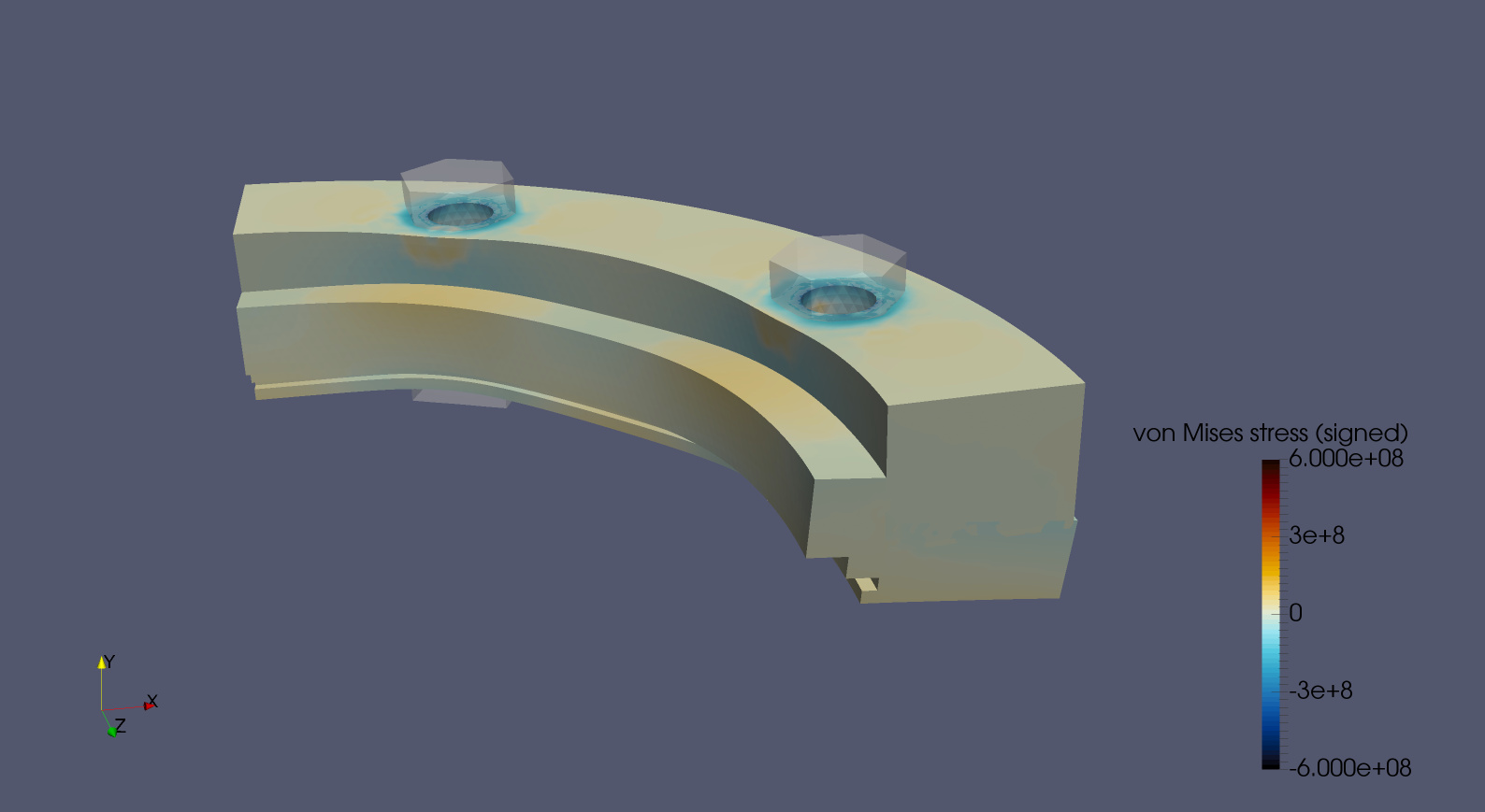
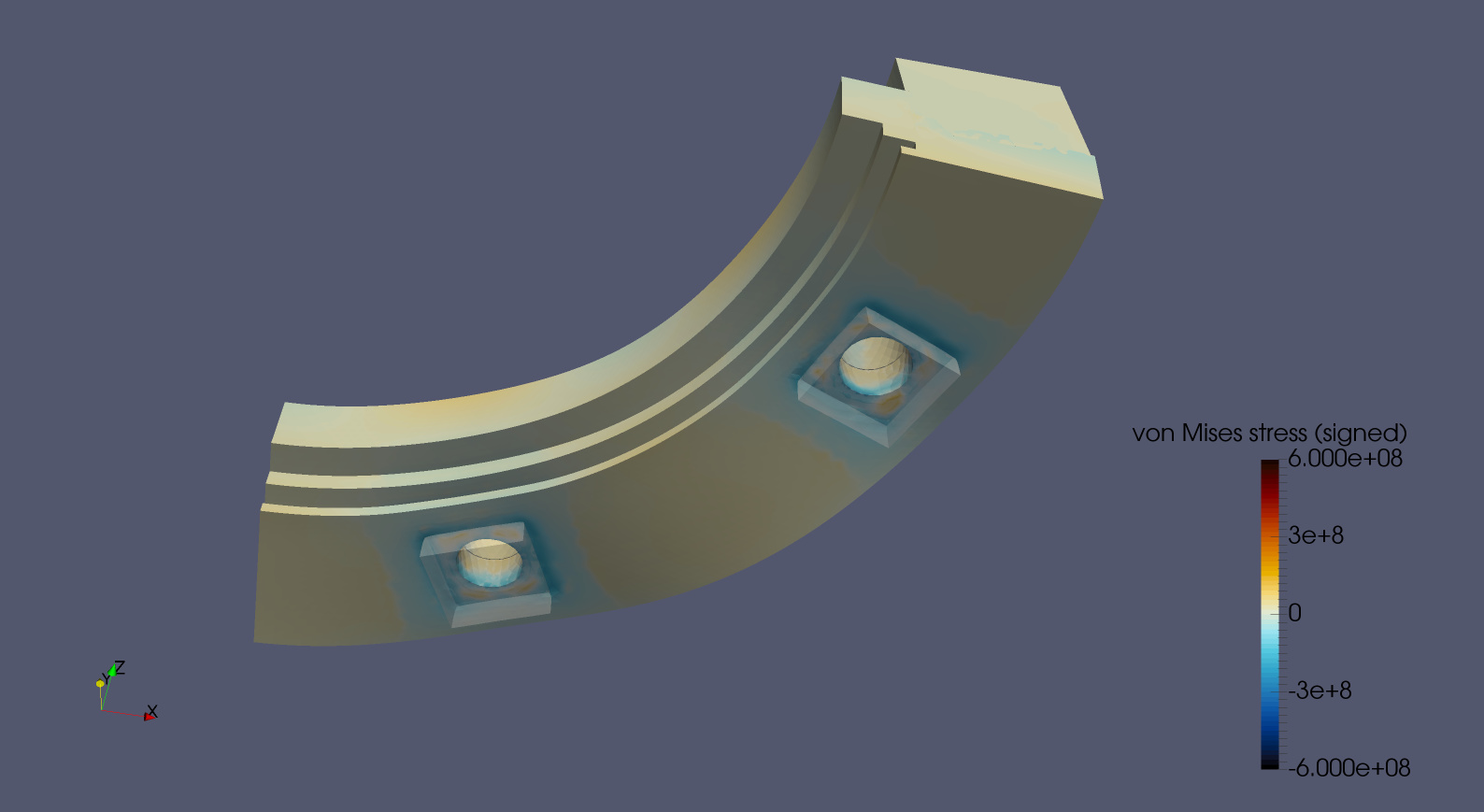
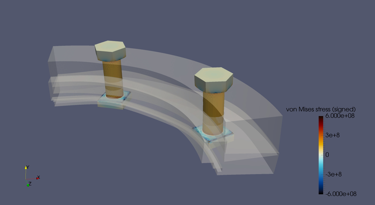
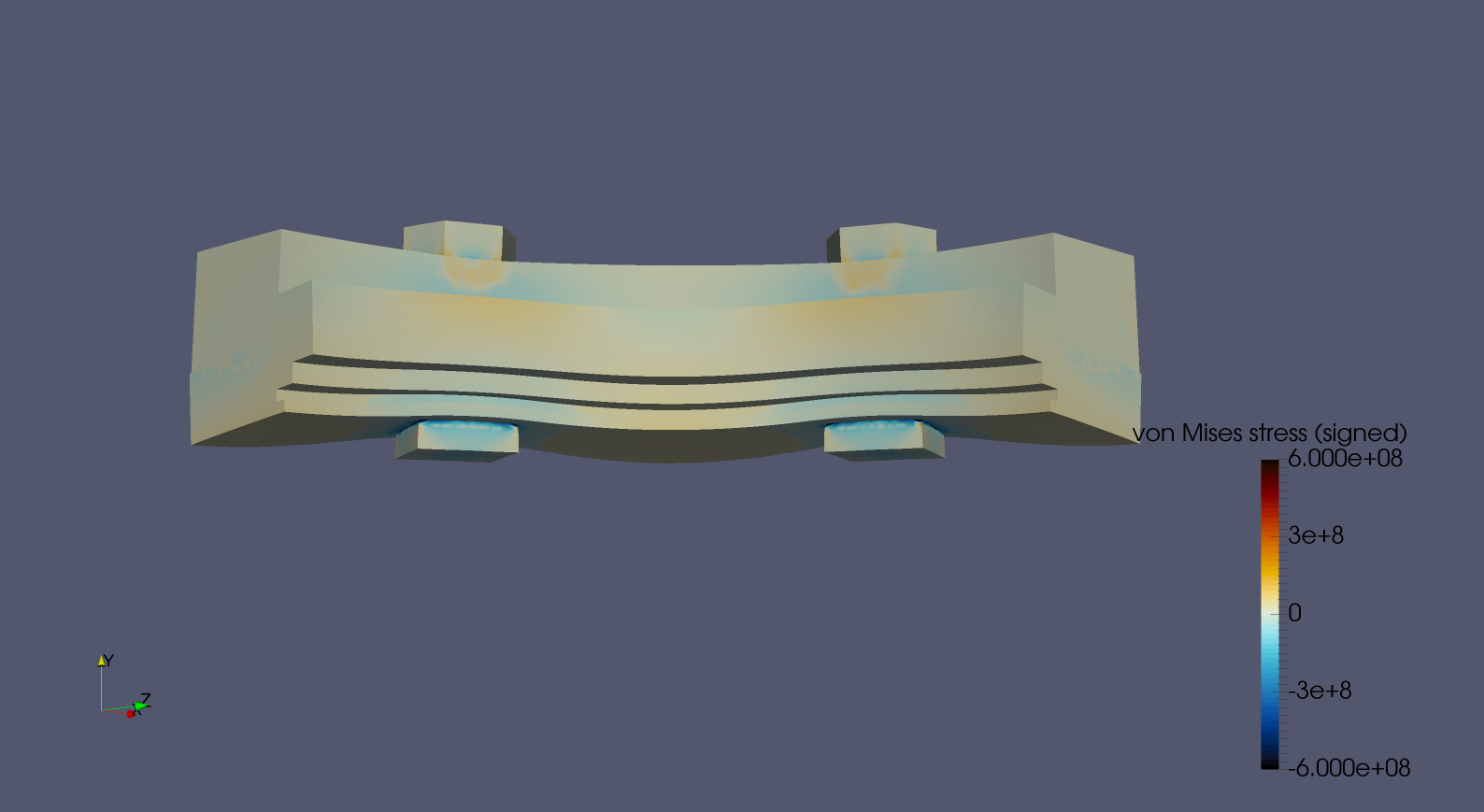
I hope this helps to get you started.
If you have any more questions please feel free to ask.
Regards, Ben
3 Likes
Hi @tsloan
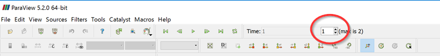
In Paraview (using current time controls toolbar):
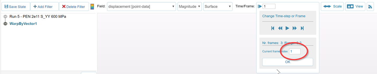
In SimScale’s online post processor (using Time/Frame toolbar):
I am skeptical about your assumption that the connection ring is fully rigid. I suspect that this ring plays an important part in the failure mechanism. Can you provide more details on how this ring is constrained in real life (drawings, photos, hand sketch etc)?
Great. Please let me know what it is.
Do you have any photos of the bolt that failed? You should be able to tell from the break whether the failure was due to excessive load or fatigue.
Can you clarify what the two rings are made of? My assumption was steel and bronze but that was only a guess from the material properties.
Regards, Ben
Hi @BenLewis
The ring is a part of a large hydraulic cylinder. The connecting ring is actually the cylinder I just made it small in the model to keep the assembly size small. I should be able to provide you with pictures today but the cylinder is pretty large and the seal is small relative to the piece it is connected to.
I’ll also be able to give you the calculated preload today I just haven’t gotten around to it.
Thanks again,
Tyler Sloan
Edit: I calculated the preload to be 736360079 Pascals. Also these bolts are 1/2-13 Grade 8 SHCS. I ran a simulation from the copy I made of your simulation which I changed the constraints in. This simulation imitates what the ring looked like in the pictures. I’m going to take pictures of the cylinder the seal is attached to tomorrow and see if we have the bolt that failed. They were also torqued to 76 ft-lb I believe. Also the seal is made of 660 bronze and i believe the other part (the cylinder) is made of 1117 CD steel but I will double check on that tomorrow along with adding pictures of the rest of the assembly.
Calculating bolt clamp force
Bolt Clamping Force (lbs.) Notes: 1. Tightening torque values are calculated from the formula T = KDP , where T = tightening torque, lb-in.; K = torque-friction coefficient; D = nominal bolt diameter, in.; and P = bolt clamping load developed by tightening.