I created a new simulation project called 'Air-conditioning simulation of an office space':
This project shows how to simulate the airflow inside an office space.
More of my public projects can be found here.
I created a new simulation project called 'Air-conditioning simulation of an office space':
This project shows how to simulate the airflow inside an office space.
More of my public projects can be found here.
In the recent spate of urbanization, there has been a rapid increase in the overall energy consumption along with a stark rise in the number of pollutants added to the atmosphere by industries as well as individuals.
Air-conditioning, a major culprit in global warming, is one of the prime causes for urban energy consumption. In the current day, offices, homes, and restaurants have installed large capacities of air conditioning to increase thermal comfort. It is up to HVAC engineers to increase the energy efficiency of the system. This may be done by studying the airflow pattern in a room/office space with an air conditioner.
Using the SimScale platform, we will simulate the airflow in an office space with an air conditioner. Based on the results of the aerodynamic analysis, we may draw conclusions to in order to achieve a similar output for a smaller energy consumption.
Analysing certain parameters, suggestions can be made regarding the most effective positions for the A/C vent and exhaust in addition to modifications in the room design.
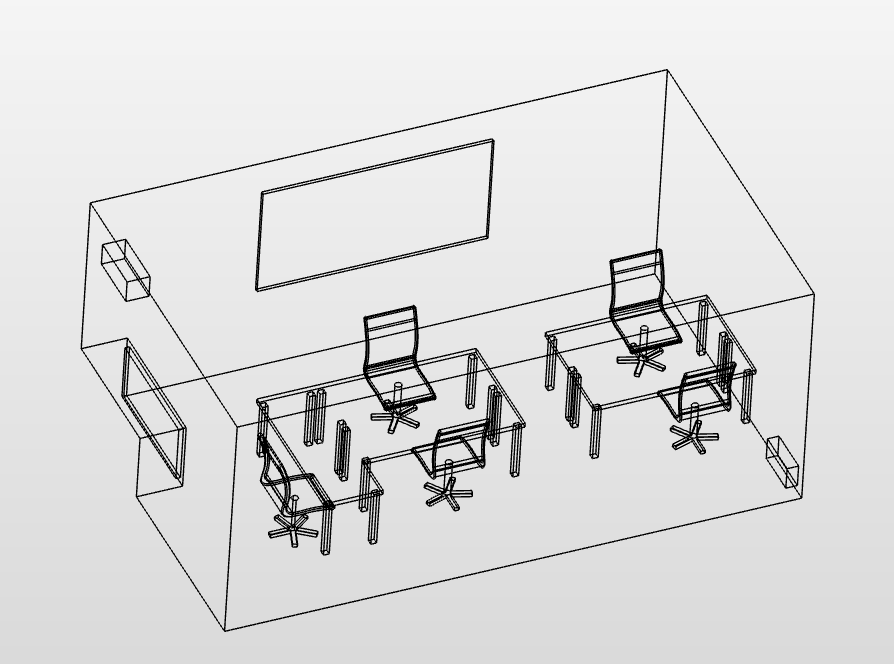
Our CAD engineers have concocted a 3D model of a typical workspace, suitable for performing a simulation. The bottom right of the room has been assigned as the vent (inlet) and the top left has been assigned to be the exhaust (outlet). This geometry is uploaded as a .STEP file onto the SimScale platform.
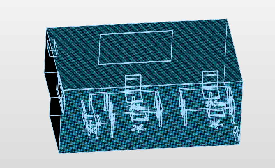
A hex-dominant mesh is created and mapped onto the geometry. Apart from the inlet and outlet, the rest of the geometry is apportioned as ‘wall’. A safe assumption is taken here: The various materials in the office interact with the air in the same manner.
An analysis type of Fluid Dynamics - Convective Heat Transfer is chosen along with a Laminar turbulence model and a Steady-State Flow. All walls are assigned a similar material (custom) stemming from the assumption mentioned above.
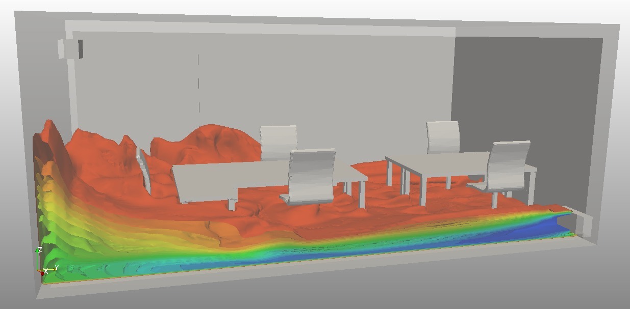
The initial temperature of the room is set to be 20°C and the pressure is equal to atmospheric pressure (105 Pa). The inlet is defined as a velocity inlet with an airflow velocity of 0.75 m/s and a temperature of 10°C. Whereas, the outlet is defined as a pressure outlet with a pressure value of 105 Pa.
i need help on designing and analysing a clean room.
Hi sgenda, try to ask a more detailed question on the forum. I’m sure somebody will reply shortly: SimScale CAE Forum
how you make the bolean geometry? some especific program?
Hi sir, i need your help in modelling an agricultural building concerning heat transfers in it
Hi @ptolentino!
You can post your problem along with a link to your model (if you have one) in the project support section of this forum. Either the PowerUsers, me or some other users will help you out then!
Best,
Jousef
Hi, why these contours are not labeled? What's the range for the velocity or temperature?
Hi @mamali14,
you are right that legends are missing in this case. Why don’t you perform post-processing by yourself and see in what range the corresponding quantities are? 
Best,
Jousef
Hello
What is volumetric heat source value for human, computers, chair, tables and for other internal components you have considered.
Dear Milad,
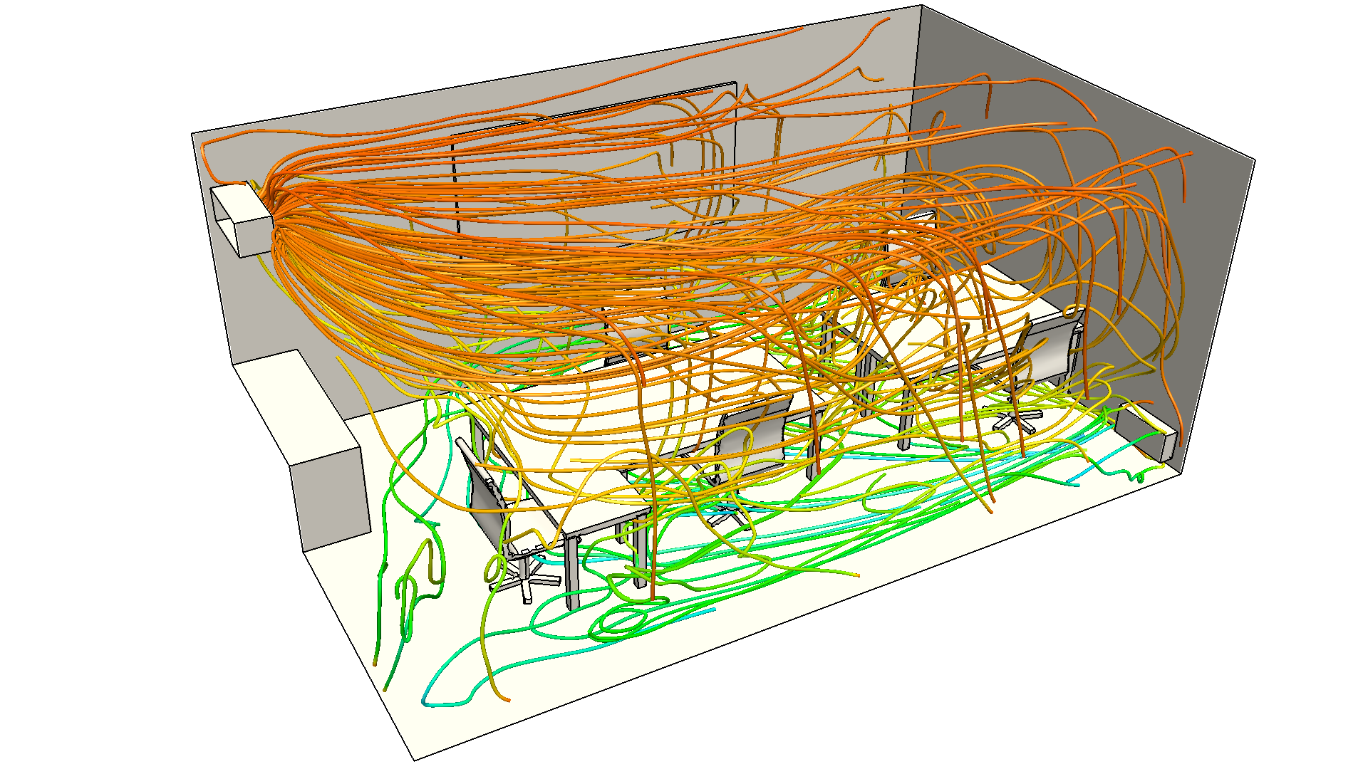
We would like to use the figure showing the air flow streamlines in a report with free distribution. Would you give us permission to use this figure. Of course we will give credit to you and SimScale in the figure caption.