Hi @dylan: Thanks a lot for the great and helpful guidelines. Concerning the *.step format, you may use the follwoing file:
One of the reasons I would like to work with face entities directly is I won’t need any refinement boxes. For example, if it is desired to reduce the cell size on and around a multi-element rear wing, I can assign a larger refinement level directly on the surface and ensure this refinement is extended for a certain distance away from the wing. Now, if I realise the wing is too high and wide, I can move the wing without moving any refinement boxes as there is none to start with.
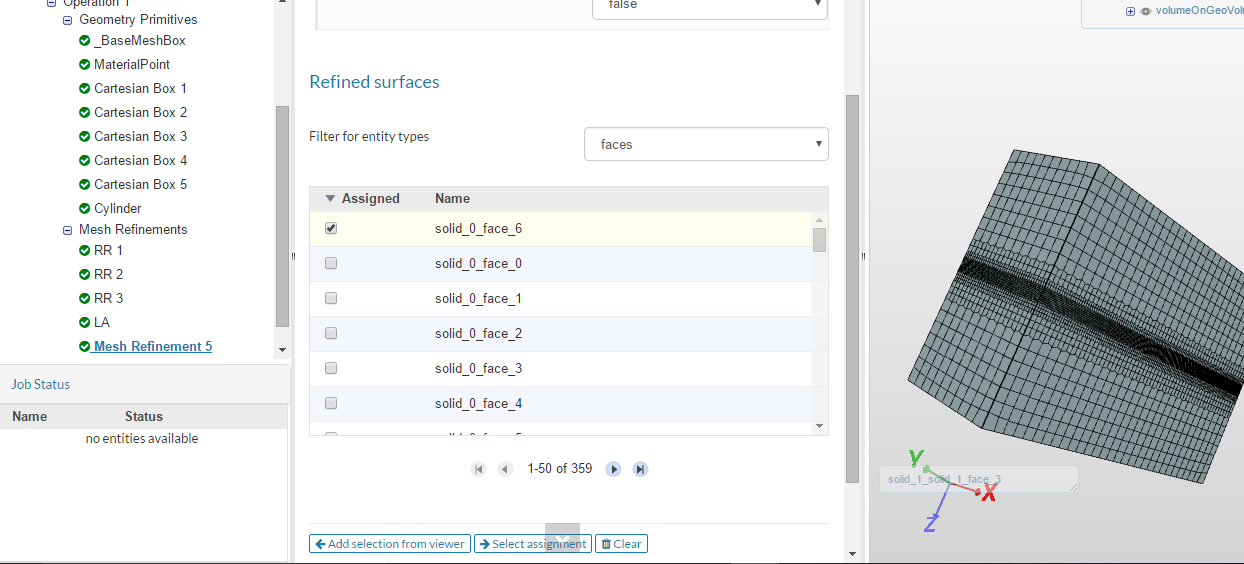
@dylan - valid point! Regarding the grouping of entities: This is done via the “Topological entity sets”. Each geometry or mesh has this points as a sub item in the tree. You click the faces together (or also use the invert selection option) and once you have the specific set selected, you hit the “Create set” button which then creates the new set that you will have available for assignment purposes in all mesh refinements or boundary conditions later on. See screenshot below
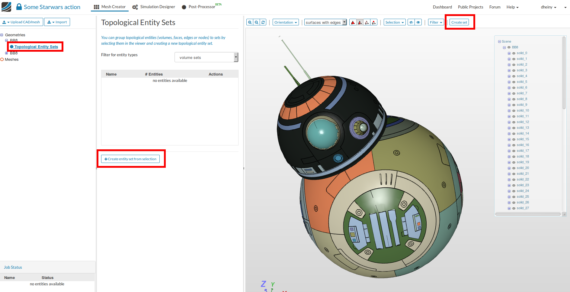
Side note: Star Wars ftw ![]() - Model from @pthomas over here: Philips awesome project by pthomas | SimScale
- Model from @pthomas over here: Philips awesome project by pthomas | SimScale
I downloaded the single car STL file and tried splitting it locally. The output file ended up with 8000+ patches. Now I am going to switch to working directly with stp/iges. 
Dear all (@dylan & @dheiny ),
I checked out the mesh log of the fine grid. The last lines are as follow:
Checking faces in error :
non-orthogonality > 65 degrees : 55
faces with face pyramid volume < 1e-13 : 30
faces with concavity > 80 degrees : 11
faces with skewness > 4 (internal) or 20 (boundary) : 2
faces with interpolation weights (0…1) < 0.02 : 1
faces with volume ratio of neighbour cells < 0.01 : 0
faces with face twist < 0.01 : 132
faces on cells with determinant < 0.001 : 11
Finished meshing with 242 illegal faces (concave, zero area or negative cell pyramid volume)
But for the coarse grid:
Checking faces in error :
non-orthogonality > 65 degrees : 0
faces with face pyramid volume < 1e-13 : 1
faces with concavity > 80 degrees : 4
faces with skewness > 4 (internal) or 20 (boundary) : 0
faces with interpolation weights (0…1) < 0.02 : 0
faces with volume ratio of neighbour cells < 0.01 : 0
faces with face twist < 0.01 : 26
faces on cells with determinant < 0.001 : 0
Finished meshing with 31 illegal faces (concave, zero area or negative cell pyramid volume)
Thanks to mention and highlight this issue which was the main problem. But I do not know what I have done wrong during the grid generation that resulted in such errors. In fact I could not split the *.stl file as a result of the high-resolution. So, I could only make region refinement.
@dylan: This is great to know that you are performing your PhD research on the aero-acoustics of a wheel. I always think how to simulate the flow around a wheel rolling over the ground. My question is how to deal with the singular point of the wheel-ground intersection (contact line). There should be a singularity as the velocities of the ground and the wheel at the contact line are different because the surface of the wheel which is in contact with the ground is flattened and we simply cut that part of the wheel. Such a singularity is also involved in the simulation of a droplet sliding over an inclined surface.
So, do you make a special consideration to overcome this issue?
Another question is that if the rotating zone in MRF can cut the boundary of the domain.
(@dheiny )
Hi
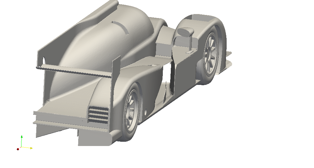
I have created a LMP with a stp file I found on Perrinn’s website during his workshop.
You can visualise zero-volume cells in paraview offline.
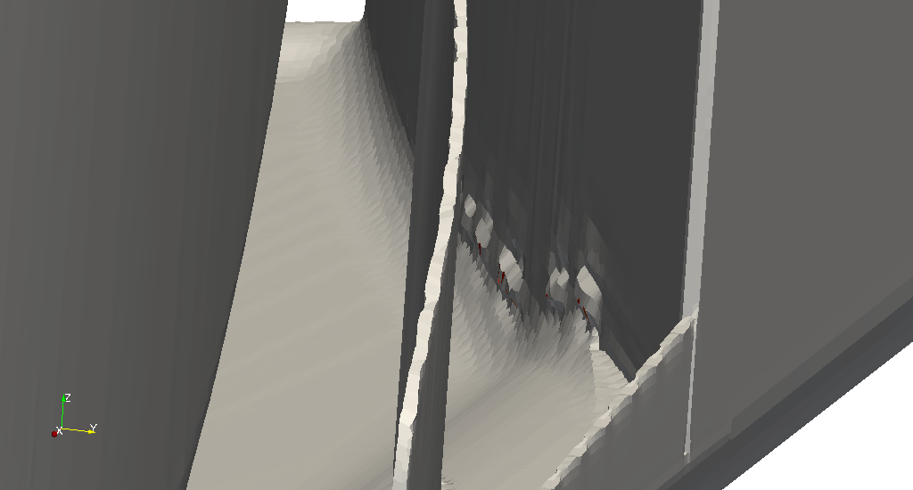
They are marked as red cells.
On a side note: I imagine you need about 50~100million cells to mesh the whole car properly when it is travelling at 70m/s, if you wish to control y+ within 30~50.
There are a variety of ways to simplify the contact patch. You can either cut a bit off the wheel, or cut it off and extrude the cut back to the original diameter creating near orthogonal corners. Diasinos has studied some effects of these simplications. The paper is part of one of the chapters in his PhD thesis.
It is difficult to maintain cell quality without the extra extrusion, but skew/non-orthogonal cells are less of an issue when located in low-gradient regions. The problem is, however, contact patches are where you see very large pressure/velocity gradients. It is important to obtain accurate results from a good mesh, although simplifications have to be made.
Wow, thanks a lot. The paper is great!