Problem: I am current working on testing the deformation of a rectangular steel plate subjected to a pressure. My projects are public so feel free to check them out. Each plate has 9 holes, 2 per each quadrant of the material and one large hole directly in the center. I test the maximum pressure the plate can withstand while keeping a factor of safety of at least 2.5. All holes besides the center one have been constrained as a fixed support. For some reason some plates with larger holes in the middle of the plate have shown to be able to handle more pressure than plates with a smaller hole in the middle. Intuitively, to me at least, this doesn’t make any sense so I’m wondering if i’m wrong or doing something wrong with the software. Again any feedback is helpful and I deeply appreciate it.
Hi @tsloan,
as a general side note, asking about the “accuracy of SimScale” with regards to linear statics is basically the same as asking about the accuracy of “Finite Element Analysis” for linear statics. This is no rocket-science and basically every FEA solver uses the same elements and principles to solve it - and thus almost all tools get the same result for such simple problems.
I have no doubt that the accuracy of SimScale is alright when it comes to linear statics.
Regarding your specific problem, could you explain the naming of your cases? Are all dimensions constant besides the center hole diameter? If I check the bounding boxes of some of your plates they seem to vary.
Best,
Richard
Hi @tsloan.
Just a small hint: make use of symmetries if possible. In your case using a quarter of your geometry is sufficient. Just pay attention to additional boundary conditions.
For a better workflow make sure that you create one project with all models and simulations in it. That makes it way easier to jump between projects rather than switching between tabs. Just give your Meshes and Simulations adequate names.
Cheers,
Jousef
For plates with the same size bore but different rod sizes, all dimensions should be the same besides the center diameter.
Hi @tsloan,
I think there might be a problem with your geometries. I checked two of your projects with different “bore diameters”
and
and combined the geometries in a single study to have a better comparison. If I load the results of the analyses both into the post-processor (right click on 2nd solution field and choose add result to viewer) it looks like the geometries have different sizes and the hole is exactly the same:
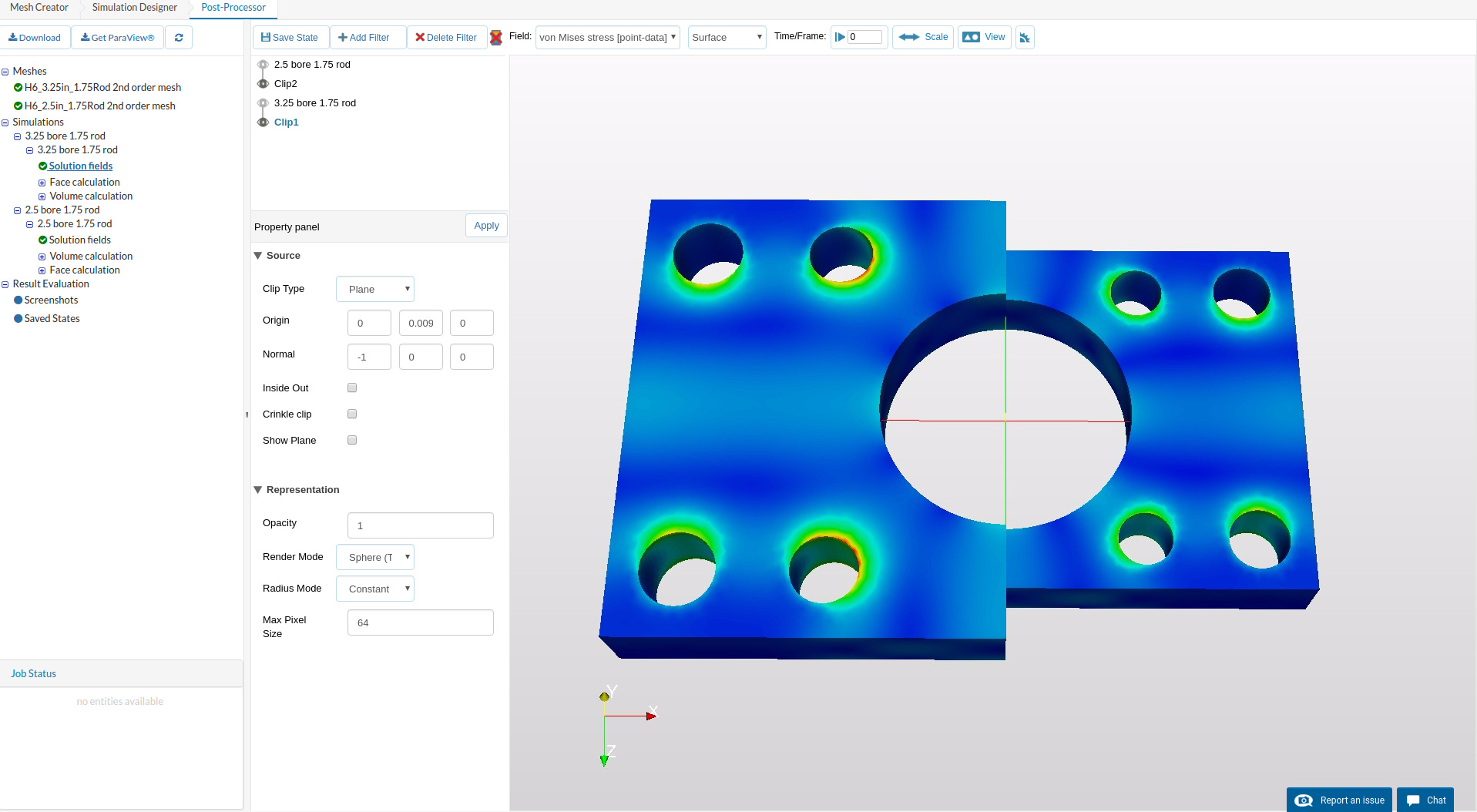
The left model is the one called “3.25 bore 1.75 rod” and on the right “2.5 bore 1.75 rod”
This might explain the unexpected behavior. You can check my project here: 3.25 and 2.5 bore 1.75 rod comparison by rszoeke | SimScale
Best,
Richard
Hi @rszoeke,
For each specific “Bore diameter” the center hole can be different sizes including center hole sizes used for smaller bore diameters as shown in your project above. My problem specifically occurs with my 2.5 bore projects where all of the dimensions for the 2.5 bore pieces are the same besides the center hole. 2.5 Bore w/ 1" rod has a center hole diameter of 2.38 inches and 2.5 Bore w/ 1.375" rod has a center hole diameter of 2.005". One would assume with a smaller center hole it would be able to withstand a greater pressure but after running it I found with a factor of safety of 2.5 that the 2.5 Bore w/ 1" rod could withstand a greater pressure than the 1.375" one which to me doesn’t make much sense. The thickness, length, width, and all other hole dimensions besides the center one are the same.
Hi @tsloan,
I took a quick look at your 2.5 Bore w/ 1" rod and 2.5 Bore w/ 1.375" rod and I have a couple of comments.
You are expecting the plate with the smaller center hole to have a the higher factor of safety and you are not seeing this. Since you are applying a pressure to the top face the smaller center hole is actually giving you a much larger total force. The “2.5 Bore w/ 1 rod” has an area of 12.26 in^2 and the “2.5 Bore W/1.375” has an area of 14.75 In^2. If you apply a 2500PSI pressure to each face the difference in force is almost 6,000lb. So, the plate with the smaller hole has 6,000lb more load being applied to it.
I am not sure if you are looking at the maximum stress in the model when you are computing your factor of safety or at some point in the model. However, you should be aware by fixing the the cylinders completely and then applying a pressure on the top surface you are artificially increasing the the stress in those areas due to the boundary conditions.
Finally, I would look at running the models with second order elements. this should give you a little bit better results.
Please let us know if you have any more questions.
Christopher
For when I calculate the factor of safety, I run it as a calculation filter using the von mises stress which gives me the factor of safety at each point. I then ensure the minimum value on the scale is at least 2.5, which I believe indicates the maximum stress. How should I adjust the boundary conditions so that it is more of an accurate representation of an actual cylinder? Also is representing the force acting on the plate as a pressure the best way to do it since the cylinder is focused at the center?
I’ll try running them with second order elements but what exactly is that doing?
Edit: Should I change the face that the pressure is being applied to?
Hi @tsloan,
if you are concerned about the superficial stress concentrations you are getting because of rigid supports, you can use the remote displacement constraint. If you leave it as deformable the constraint itself won’t add any stiffness to the model. You would need to add a constraint to each one of the fixations and put the remote point at the COG of each of the cylindrical faces. Then you can even constrain the rotations (or leave them free). I would actually leave the rotation free for the cylinder axis rotation and fix it for the other two.
I guess a pressure is fine, as long as this is what actually happens in your real application (like a constant known pressure).
Using second order elements will greatly increase the accuracy of the stress computation. In cases of pure bending this might well be in the range of up to 50% difference. Usually first order elements are approximating the displacements quite good, but are underestimating the stresses (you can also have a look at this forum post which highlights similar projects where second order elements were needed: When should I use a second order mesh?).
Best,
Richard