Dear SimScalers,
in this week’s spotlight, we take a look at a finite element simulation of a 3D printed transmission support by our user Maximilian (@pumuckl007).
\underline{\textbf{Introduction & Problem Specification}}
Max wanted to create a transmission for a small cart in Onshape and attempted to 3D print the part. Realizing that this would take longer than the time he was allowed to use the 3D printer, Max decided to optimize his design with FEA. By using SimScale, he could figure out how much material he could remove to reduce the printing time by two hours and managed to 3D print his part on time.
He planned to mount two of these transmissions to the bottom of a wood plate on which there will be an 8-bit computer which he has modified to allow motors’ control. The third wheel will just be dragged behind the other two.
Using FEA with SimScale, Max was able to reduce the 3D printing times by one third by removing excess material! At first, he was using a 1cm wall thickness for the outside, but after running a simulation with a 0.5cm wall, he realized that this would be more than enough.
In addition, he analyzed two other parts. A large and small wheel to make sure that they would be strong enough.
This project spotlight is divided into the following parts:
-
Geometry
-
Meshing
-
Simulation
-
Simulation with SimScale
-
Results & Conclusion
\underline{\textbf{Geometry}}
Format: STEP
This simulation is part of a transmission which can be found here: Transmission model − Onshape
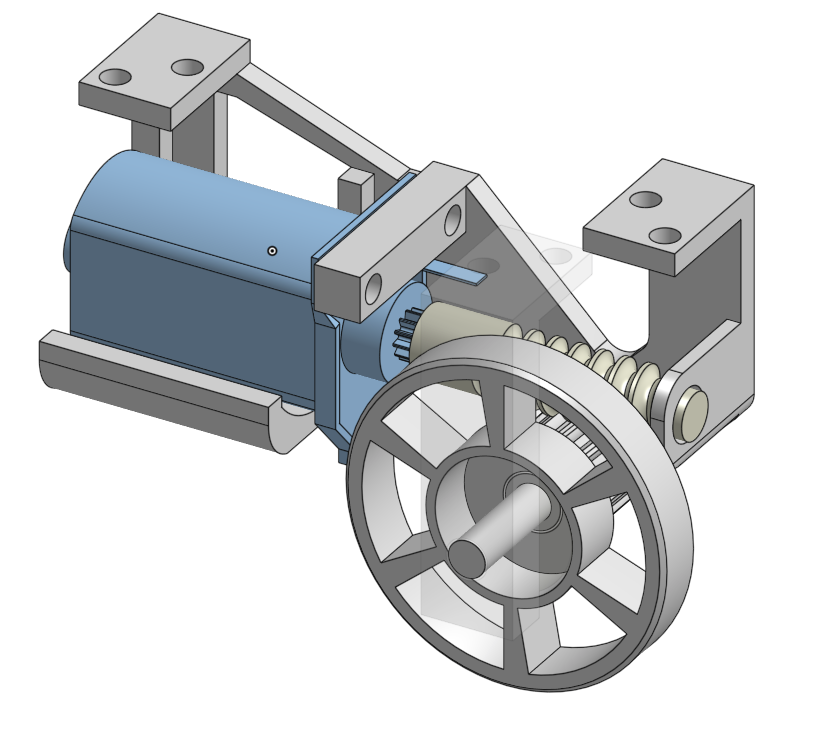
Figure 1: Onshape model
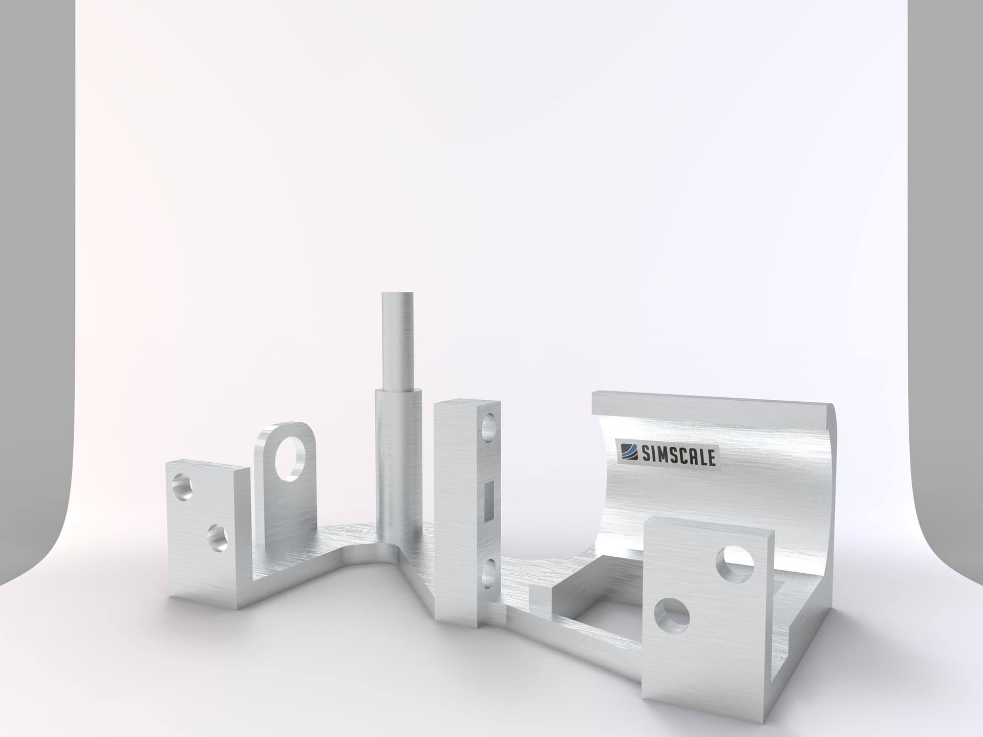
Figure 2: KeyShot rendering
\underline{\textbf{Meshing}}
Type: Tet-dominant
The mesh of the model was executed with the Tet-Dominant all-round meshing algorithm, mostly dedicated to structural mechanics, which can also be used to generate tetrahedral meshes with boundary layers for fluid flow analyses.
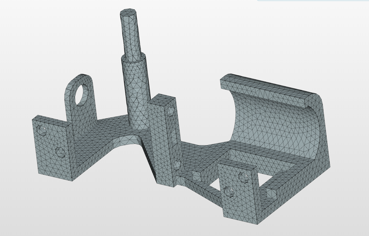
Figure 3: Tet-mesh of the transmission
\underline{\textbf{Simulation}}
Type: Static Finite-Element Simulation
\underline{\textbf{Simulation Details}}
\underline{\textbf{Materials}}
\underline{\textbf{Boundary Conditions}}
The initial condition (time = 0s) is illustrated by Figure 4, with the EAF of about 40 tons of liquid steel, the condition of stopping the arrival in the liquid foot. In the case of the analysis of an incompressible, transient and non-heat transferable fluid:
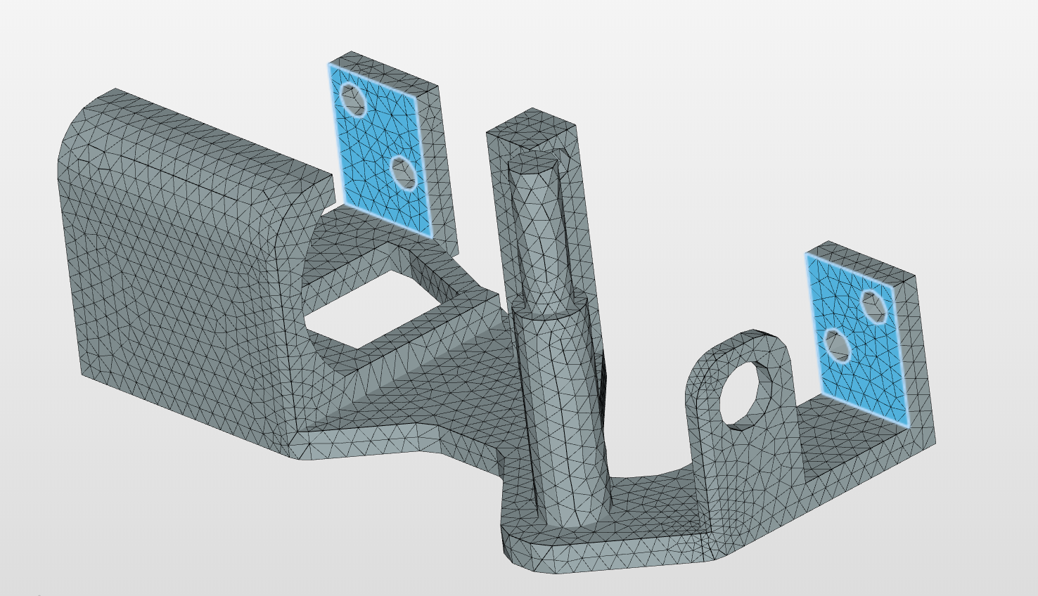
Figure 4: Constraints responsible for simulating the plate
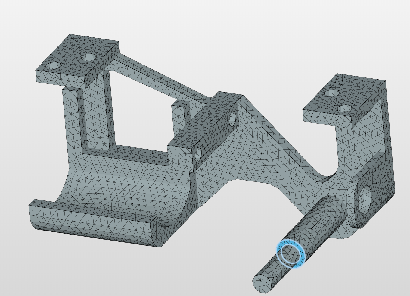
Figure 5: Constraints responsible for simulating the wheel
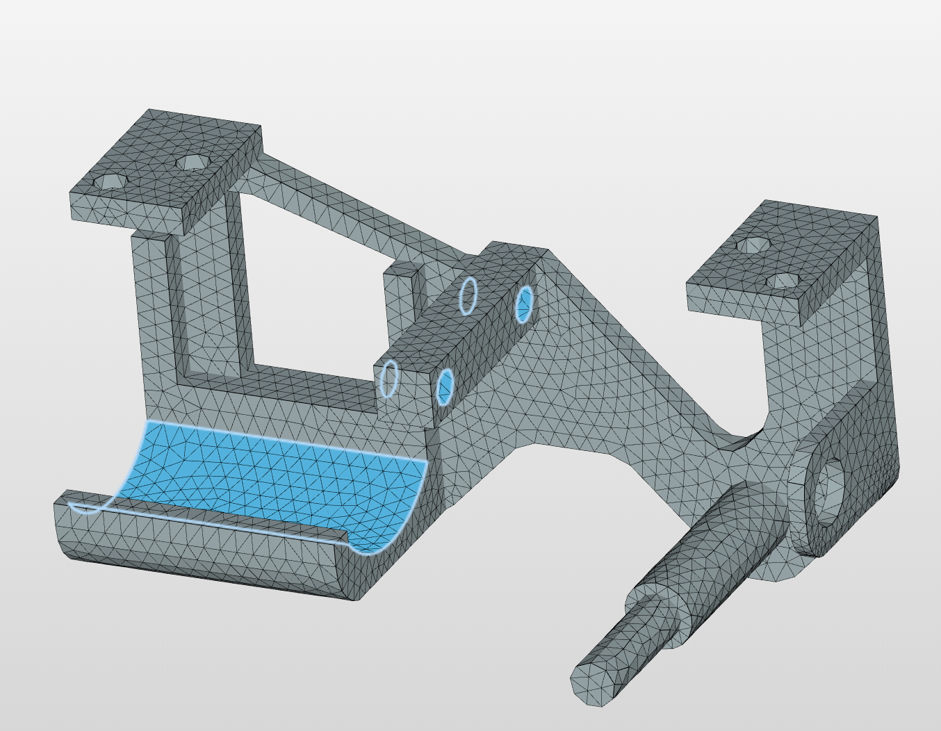
Figure 6: Constraints responsible for the simulating the motor
\underline{\textbf{Solution}}
Machine cores: 4
\underline{\textbf{Numerics}}
Numerical settings can be found in the project!
\underline{\textbf{Results & Conclusion}}
\underline{\textbf{Displacement}}
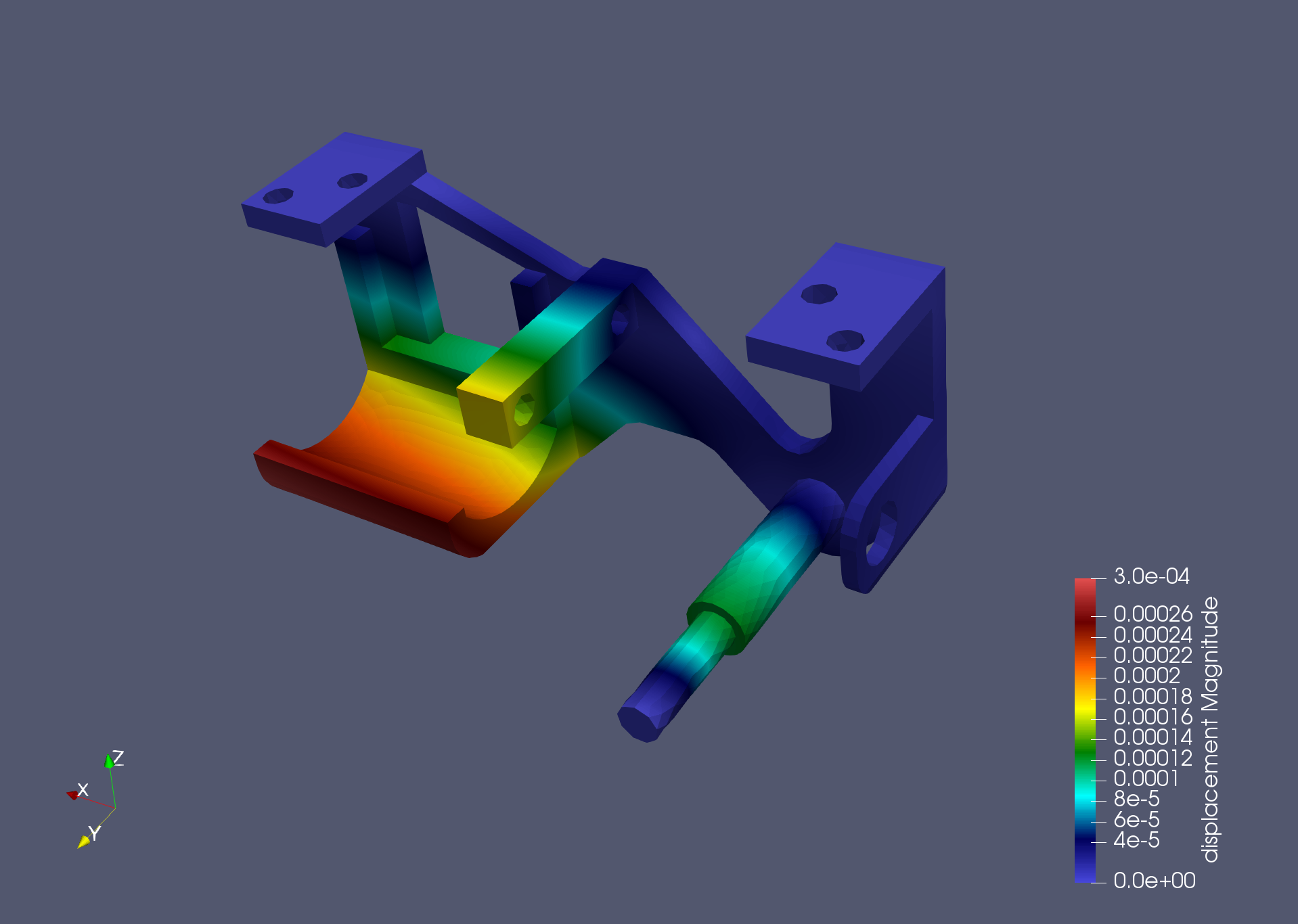
Figure 7: Post-Processing of the Displacements
\underline{\textbf{Von Mises Stress}}
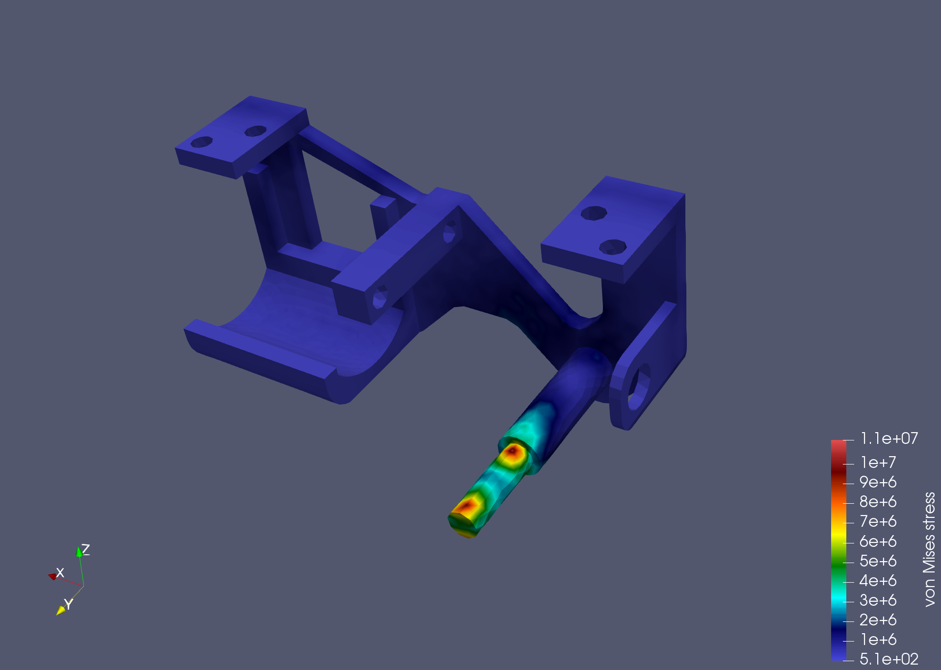
Figure 8: Post-Processing of the von Mises Stress
The simulation stated that a maximum deformation of 0.3mm would occur and that the stress would be low enough not to cause inelastic deformation of the material.
The simulation results matched the behavior observed in real life with the transmission assembly.
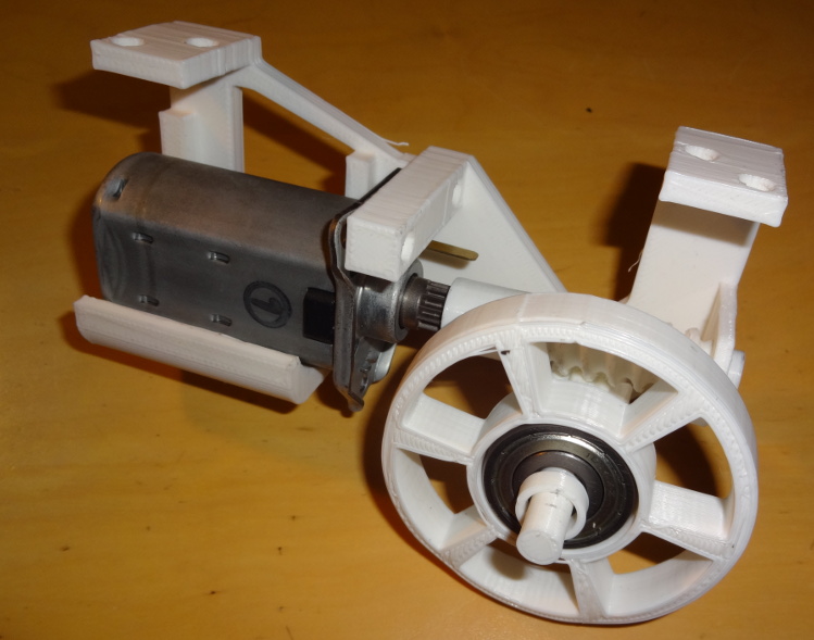
Figure 9: Final version of the 3D Printed Transmission Support
\underline{\textbf{SimScale Project}}
To see the simulation setup, please have a look at the project from @pumuckl007:
To copy this project into your workspace, simply follow the instructions given in the picture below.

\underline{\textbf{Visit our SimWiki by clicking on the picture}}