I created a new simulation project called 'resistorassyinbox':
thermal analysis of resistor in fixed environment
More of my public projects can be found here.
I created a new simulation project called 'resistorassyinbox':
thermal analysis of resistor in fixed environment
More of my public projects can be found here.
Hey @kturnbull,
nice resistor model. I had a quick look at your project. Two things got to my attention in the setup. First, the model consists of multiple solids, which is fine of course but in order to connect those different parts of the domain one would need do define contact constraints between those parts. Second the model seems to be intersecting for the outer parts. That is why there are two different mesh parts at the bottom plate.
I’ll have a look at the geometry model and come back to you soon.
Best Alex
Hey @kturnbull,
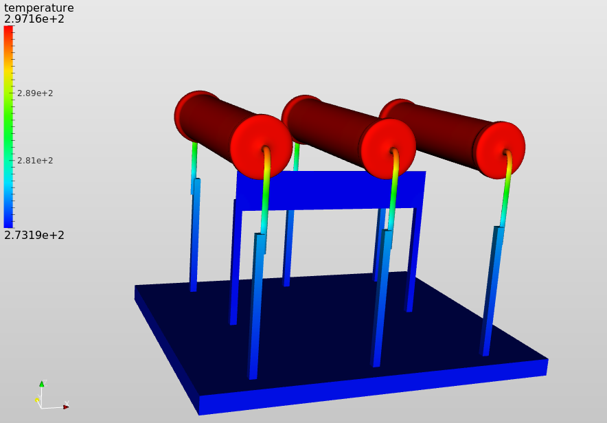
sorry for my late answer! I had a closer look at the setup. If one runs this analysis with a finite element analysis based on the heat transfer equations (Heat transfer analysis) it makes sense to cover the convection by a convection boundary condition. That means the environment (in this case air) is not considered in the domain but the convectional heat transfer is applied on the boundary faces of the geometry. I did that, while also changing the geometry slightly to showcase the different types of connections that are possible and in order to be able to address the resistor volume as heat source. Below you find a screen shot of the temperature field assuming every resistor represents a ~1W heat source (the value in the bc is derived from 1W in total divided by the resistor volume).
(resistorassyinbox by afischer | SimScale)
I saw on your profile page that you already made quite some progress on your own, so some hints might be deprecated ;-). As your geometry is well suited for showcasing the different types of connections, would you mind if I would write a forum post explaining those connections in detail. It feels like a lot of community members have troubles at the beginning setting those up properly.
Best Alex
Hi @afischer
Thanks for your efforts I appreciate all the help I can get as you would have gathered . Feel free to use this example in a forum post. As a side note I think this model would be a good puzzle to solve for all professional and budding thermal engineers, what resistor power dissipation trips the thermal fuse if the fuse solder melts at 180-200 deg C? and I could sit back and watch the professionals solve!. would that be cheeky?lol . The actual assembly is built slightly different ie using spring like coil wire with no core or heatsink but the principles of analysis is what i’m trying to achieve. I believe there is an issue with the design and may cause false tripping hence my interest. I am looking at transient analysis and hope I can see something happening when in the real world the cooling fan stops but the heat remains for a finite time in the assembly!. Interesting problem I think!
Does simscale give calculated part volumes for users to use in calculations or will I need to go to back to my freecad model s/w TIA?
Regards
Keith
Hey @kturnbull,
thx for your help, I added a forum post in the FEA / Solid mechanics section: Connecting domain parts in FE analyses
Right now the volume information of part volumes is not provided in the workbench. It would be easy to add that in the event log for example. But I think a better approach would be to add a heat source boundary condition where we calculate the corresponding W/m³ value before the simulation automatically. Thus we would take that step away from the user as we have the information about the mesh volume parts anyways. We do something similar with force boundary conditions in the mechanical solver. What do you think?