Hi Dusan.
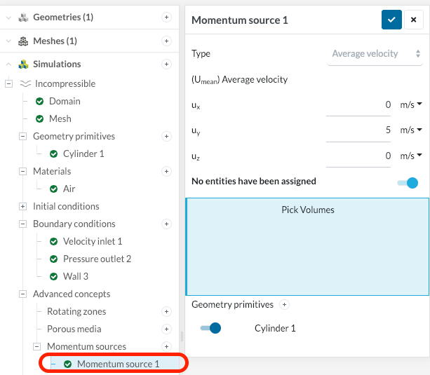
First about the cylinder settings and the “missing” boundary conditions. Momentum sources can be used to simulate fans, ventilators and other similar devices. Whilst normally, the user would have to provide a detailed geometry and a fine mesh of these components, this feature allows one to define a volume which generates momentum, without any further complication.
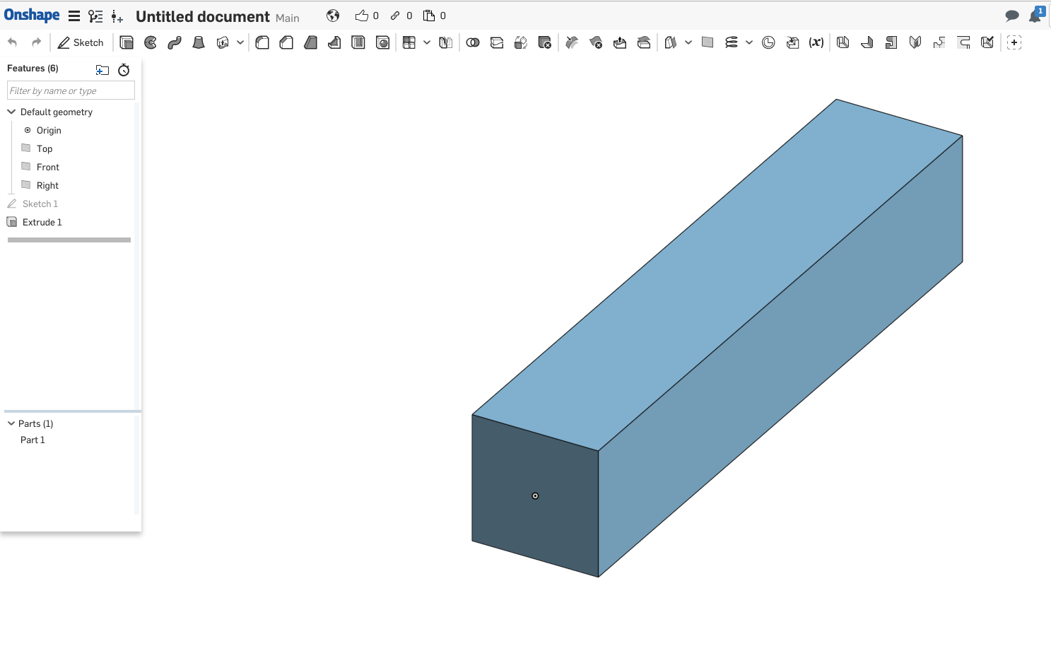
\underline{\textbf{1. Create the box with OnShape}}
I ignored the recommendations from the paper in the beginning and just created a bigger domain by intuition. Feel free to follow the paper and see if the size has an influence.
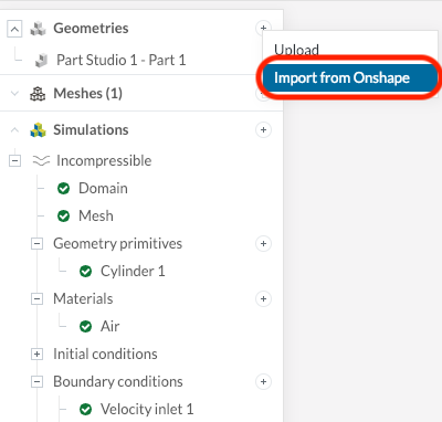
\underline{\textbf{2. Upload the geometry via Onshape plugin on SimScale}}
After the message “successfully imported” appears you can close the tab.
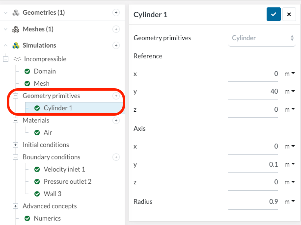
\underline{\textbf{3. Create the cylinder}}
\underline{\textbf{4. Add the Momentum Source}}
All the best,
Jousef