I’m confused about the results you shared in your previous post. Here are my observations:
The pressing plate moves vertically a distance of 2 mm, but your plot shows a maximum travel of just over 2.5 mm.
There is a 1 mm gap between the free end of the spring and the fixed sliding surface. From geometry, the pressing plate will move approximately 0.5 mm vertically before the free end of the spring engages with the fixed sliding surface. Your plot shows this engagement occurring at around 2 mm.
Your spring rate (once engaged) is very high compared to the results obtained with no gap. I would not expect such a large change.
Maybe I have misunderstood your application. If so, please let me know.
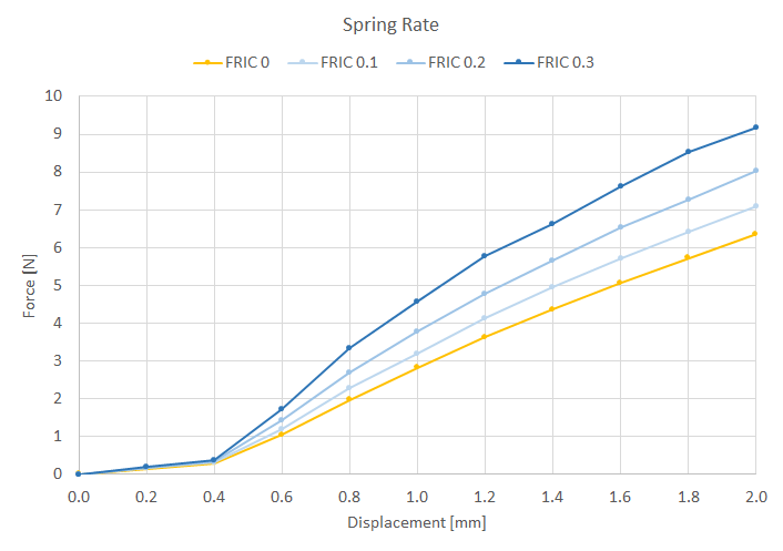
I’m not sure what the friction coefficient for beryllium copper on steel is. As such I have run your simulation with three levels of friction. The results are shown in the plot below. This plot shows the sensitivity of the system to the level of friction.
These simulations take quite some time to solve (anywhere from 6 to 10 hours depending on the level of friction). However, I have found the current setup to be quite robust so I would stick with using a second order mesh with physical contacts.
I have to apologize, just now found out that the gap in my new spring model is actually 2.5mm wide, not 1mm. My engineer got that info from the manufacturer but didn’t tell me, just gave me the new CAD model (the spring is also shaped slightly different to the first one, to reflect the true shape better). So to me it appears that both results were correct, just for different situations… However, if there is some obvious mistake in my simulation setup I’d be really glad to know since i don’t know many of the details of the process yet…
Thanks again for your help,
best regards,
Peter
Your setup looks pretty good. If you have trouble with convergence or you want to reduce the solution time you could try some of these changes.
Reduce your penalty coefficient from 1e14 to 1e13. This will result in slightly more penetration between physical contacts but will solve quicker. I found the penetration with a penalty coefficient of 1e13 to be quite acceptable. You may want to try reducing this even further to solve quicker. It’s a bit of a balancing act.
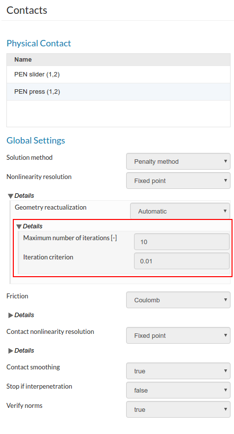
Increase the maximum number of fixed point friction iterations from 10 to at least 20. This will help with convergence. You will find this setting under Domain > Physical Contacts > Friction > Coulomb > Friction nonlinearity resolution > Fixed Point > Maximum number of iterations.
Increase your mesh size so that there is only one element through the thickness of the spring. This is not recommended for first order meshes but I generally get good results with second order meshes. The settings I used were - Maximum element edge length [m] = 0.0002, Minimum element edge length [m] = 0.0001.
Reduce the size of your slave surfaces as far as possible. The less slave nodes the quicker your simulation will run. To do this you will need to split your slave surfaces in your CAD tool.
Reduce the number of computing cores from 32/16 to 2/1. This simulation does not require much memory. This will save you core hours.
Change your time step definition from auto to manual. When your settings are correct you will not need auto time stepping.
I hope this helps. Please let us know how it goes.
Not sure here though. With second order this machine combination could be small. 1 core will work way slower. If the memory distribution is not a big problem considering there are less DOFs, I would recommend to use MUMPS on 8/4 if the mesh size is bigger than 60K nodes otherwise 8/2. This will decrease the computation time at least two times if not 4.
i’ve done a couple of runs and run into a problem: there’s a warning about my mesh (orphan nodes), which makes some runs fail, while others complete without problems. Looking at the solver log, I don’t really understand what the problem is (apart from the fact that I should try a different mesh). Could anyone please explain to me why my simulation runs failed?
One more question: I’m now using different different CAD models for simulations which differ only by the position of one plate (the slider fixation plate, i. e. the plate where the free end of the spring slides). Would it be possible to get different situations by simply using the displacement mechanism for that plate? Like, a fixed (in time) displacement of this plate in Y direction for each run?
best regards,
Peter
The error occurred since the solver exceeds the fixed point iterations and not due to existing orphan nodes which is just a warning in this case. The error says:
!-----------------------------------------------------------------------------! ! <BoucleContactError> <MECANONLINE9_11> ! ! ! ! Stop by failure in the loop of point fixes on the statute of contact. ! ! The total base is saved. It contains the pitches archived before the stop. ! !-----------------------------------------------------------------------------!
The reason of termination after this divergence is the use of ‘Manual’ timestepping scheme. In the case of Manual, solver will not try to cut down the timestep in order to get convergence. You can switch it to ‘Auto’ in order to make the simulation running even after this divergence. Please note that simulation will take a long time as it already did in order to reach the final time and it may fail also after that.
Furthermore, looking at one of your results your stresses looks odd. The main reason is that your mesh is quite coarse. You may need to reconsider mesh refinement here.
For an easy convergence, you can consider increasing the iteration criteria to 0.05.
@ahmedhussain18
Thank you for your quick reply. I agree that the mesh is rather coarse, my idea was to start with something less demanding in processor time and then move to finer meshes… What do you think about my second question?
Yes you can do that. All you have to do is to initially move the plate along y-axis via function definition and make it constant afterwards. And then start moving the lower plate. For example, giving 0.0012t*(t<=0.5)+0.001*(t>0.5) under y-direction formulation will move the upper plate to 1 mm until 0.5 sec. and then it will remain there afterwards.
Then your lower plate formulation would look something like this: 0.002*(t-0.5)*(t>0.5) when you run the simulation until total time period of 1.5 sec..
That sounds like a bit of a complicated solution to me… isn’t it possible to just set the displacement of that plate to 1mm (with no time dependancy)? I’d prefer to have only one displacement of that kind per simulation, and keep the time dependancy for the pressing plate.
please see the following simulation in my public project [!!!THIS LINK IS NO LONGER AVAILABLE!!!] :
Spring12 - REM - Run 8 - DY 430e-5 T1 0.24
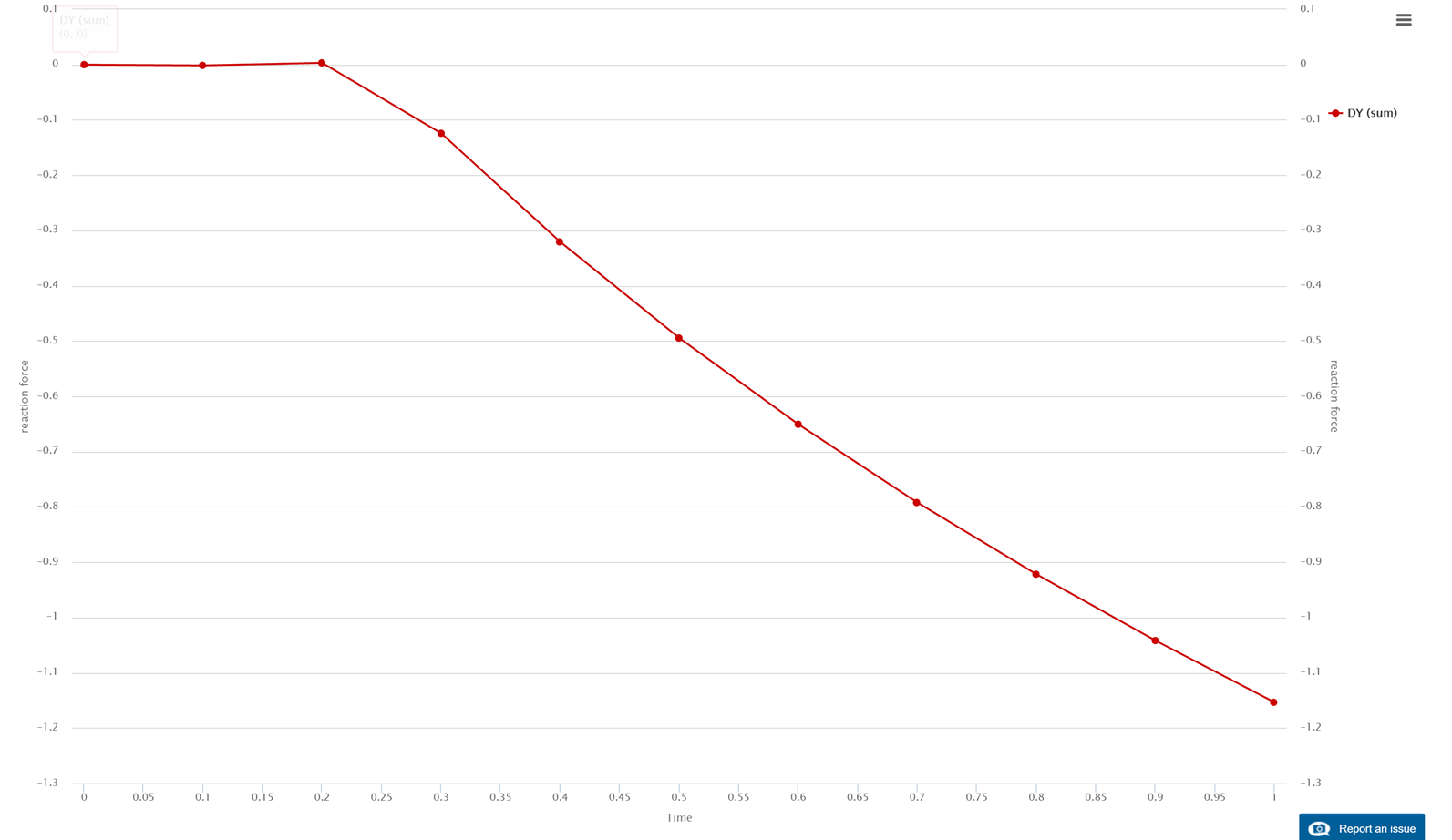
This simulation is set up to do what you are asking for. This approach is very quick but you cannot use friction. You also have to tune the vertical translation rate of the fixed silder so that there is no force applied to it in the first (non contact) stage of the simulation (see plot below).
@pborgens, yes you can do that in the very first timestep by giving the displacement value directly 0.001 which will actually perform something like this 0.00110t*(t<=0.1)+0.001*(t>0.1). Make sure then you ramp the moving plate as 0.002*(t-0.1)*(t>0.1) otherwise it may diverge or may not even following the older method. This case is easily doable while in absolute error convergence criteria whereas the solution initially diverges a lot in case of relative convergence criteria. Reason? no forces in the system. Also make sure to switch to auto timestepping before doing this.
I got confused about what you were asking for. Now that I understand I can see my answer does not make sense. The approach suggested by @ahmedhussain18 is the right one. Sorry about the confusion.
Hi again,
I decided to revive this old project after taking a long break from simulation problems in general due to being very busy with experiments. This time i want to move the “pressing plate” horizontally, sliding against the spring, in contrast to pressing the spring from the top (see the last simulation, “Type 2 gap 2.5mm no fric”). After making a new CAD model and mesh, i tried to set up the simulation, first without any friction. However, i run into a “singular matrix” error, and would be thankful if anybody could give me a hint how to fix it (and maybe additional optimization hints/ideas). Any help would be much appreciated!
Hey @BenLewis; I know this is an old post, but I was reviewing your solutions and I had a general question. I noticed you used a Fixed Value boundary condition to constrain the midplane for symmetry (FIX_X Symm (3)). Could the same thing have been achieved using the “Symmetry Plane” Boundary Condition with that X-plane defined as the symmetry plane? Or am I misunderstanding the use of a symmetry plane boundary condition for this type of application?
thanks @Ricardopg and @BenLewis; those explanations make sense. I’ll reserve symmetry for models with symm planes non-normal to global axes (and double check the constraints on shared nodes!)