Glider CFD Project

Hi
I’ve just started using SimScale and I want you guys help me completing this project.

The aim of this project is to illustrate the flow around a glider.
However, I’ve been having an issue with either meshing or CFL.
On Run-5, I tried to run it by decreasing the mesh fineness but it didn’t work.
By anychance anyone could check my project from the link and have a look into it please?

Project Link: SimScale

Thanks in advance!

1 Like

Hi @SalmonMan and thanks for reaching out to us!

My colleagues @DaleKramer & @jhorv_th were working on a glider project and give you some good tips if your setup is good or not. CFL and the mesh are connected but it can be that only your mesh has some erroneous elements in it causing either the mesh or the simulation to crash. CFD Squad, let us know if you have additional impetus for our user.

Best,

Jousef

2 Likes

Hi @SalmonMan,

thank you for reaching out!

You realized that you can use symmetry constrain, and it’s good! :slight_smile:

At the first sight you have issues because of the too coarse mesh. The error message also suggests that we have the problems somewhere there:

In order to capture the geometry, a more refined mesh is needed.

I would first check the bounding box size and position. I think for simple flow visualization it is too big. Also, I’d put the object farther from the inlet.

Another important aspect is that the mesh element is preferably cubic, all edges are the same length,

In the area of the object, different refinements are needed to ensure that the mesh describes the geometry well.
You can read about or check different public projects to have the feeling.

If you’d like, I could make a draft mesh which you can use or improve further.

Don’t give up, CFD takes time to learn and more to excel. :slight_smile:

Best regards,
János

4 Likes

Hi! Thanks so much for having a look into my project!

Alright, so I’ll try working on the meshing more.
Now I think I know what I’m doing:sweat_smile:

If I still have a problem with it then I may reach you out again but I’ll try myself first:+1:

Thanks again for the helpful reply!

Kind regards
Taichi

1 Like

hi @SalmonMan

I checked your model and there are 12 knife-vertices that make problem in your simulation. so, remove that first. :grinning:


if you are Solidworks user than before you go for any simulation you can check your geometry in Solidworks.
click on evaluate > check geometry

Cheers!
Rohit.

1 Like

So here I’ve tried re-meshing.
I had a look into this public project: SimScale

However, it still looks like the area around the surface is quite rough.

What I want/need is something like this if I’m not wrong.

I reckon there’s something to do with ‘inflate boundary layers’ though…

Taichi

Hi Rohit

Thanks for having a look!

Alright, the model is actually made my friend but I’ll do that on my Solidworks.
Thank you for the tip!

Taichi

1 Like

Hi @SalmonMan,

I’ve made a quick and dirty simulation on your geometry: SimScale.
For simplicity I chose automatic mesh generation which is far from the ideal (too fine far from the object, too coarse close to the object).

It works, can be used to represent speed and pressure distribution or fancy streamlines.

If you need to acquire lift and force data for your RC project than indeed, correct boundary layer inflation is needed as you guessed.

You can find a lot of discussion about the “y+” topic and a lot of public examples on this site.

I suggest to read this thread: SimScale

I think this mesh is pretty good: SimScale

Keep up and best regards,
János

6 Likes

Hi Janos

That’s awesome!
Thanks for the info. I’ll learn from those projects and try:+1:

Kind regards
Taichi

3 Likes

Hey Taichi,

There are a bunch of y+ calculators online, like this one from cfd-online or this google spreadsheet. These are reliable but I do recommend that you make your own spreadsheet for y+ evaluation.

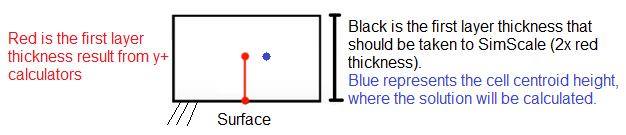
So basically these calculators take a desired y+ as input and return the thickness of the first cell. It gets a little bit tricky here though, because a lot of solvers, SimScale included, calculate the solution at the cell centroid. So you should multiply the calculated first cell thickness by 2 before taking it to SimScale.
Just to give an example, let’s say the calculator returned a value of 0,002 meters for the first layer thickness, If you input this value to SimScale, the solver is going to calculate the solution at the cell centroid (0,002/2 = 0,001 meters) which will result in a y+ that is too low. By multiplying 0,002 meters by the factor of 2, your first cell centroid will be correctly placed at the desired 0,002 meters mark.
image

Hopefully I could get my point across :sweat_smile:

/Ric

11 Likes

Hi Ric

Thanks so much for that!
That’s really intuitive and and clear for me to understand.

1 Like

After bunch of trials and errors, I eventually managed to run a calculation with another type of aeroplane that my friend’s designed.
I’ve only used Paraview for post-processing so I’ve no screenshots yet but hopefully it’s ran well:grin:

1 Like

YES!!
I guess it was pretty successful.
Thanks so much for your help guys.
I’ll still try on the original glider project as well.

Taichi

4 Likes

Wow, finally someone who has answered WHY I have never been able to have my yPlus surface mappings match the yPlus I was shooting for with SimScale…

You need to become a PowerUser :wink:

Thanks,
Dale

4 Likes