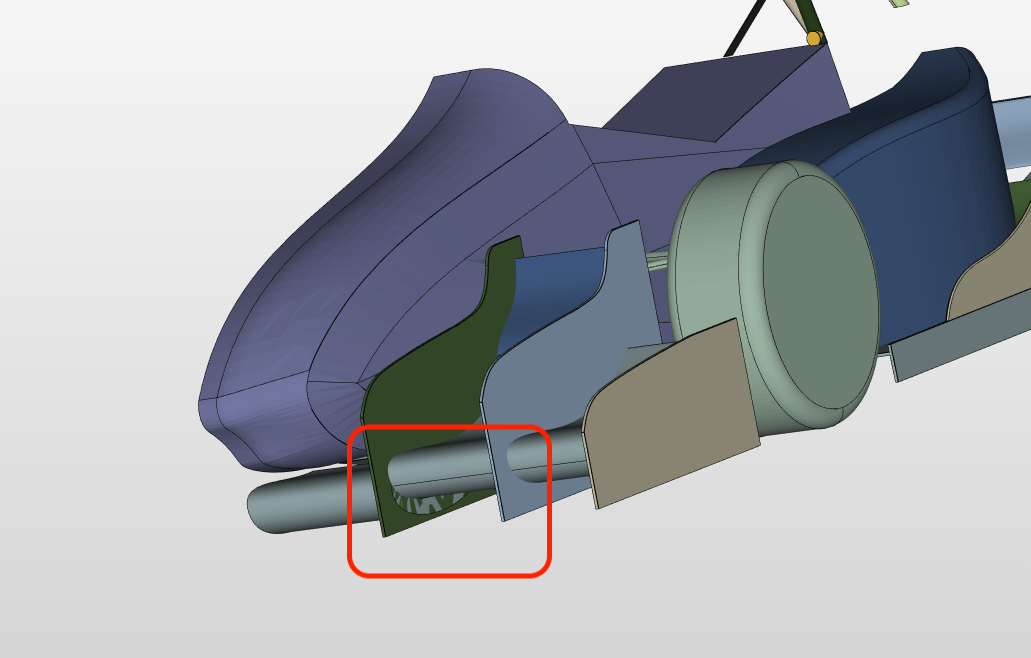
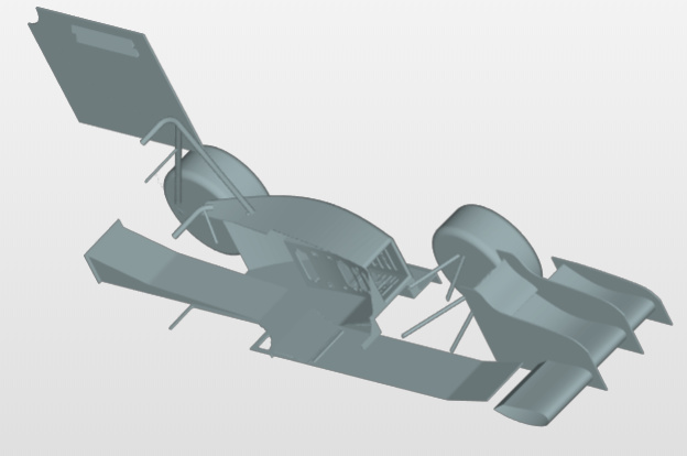
No worries! First of all make sure that your geometry is watertight as well as avoid overlapping surfaces! I can see some overlap in the front of your car for instance. Decreasing the number of cells was just mentioned as you have way too much cells at the moment (as you noticed it takes very long to load the mesh) - so lowering the refinement levels can definitely help!
For the number of cells no general statement can be made - that differs from case to case and is not the same approach as in FEM.
In general you perform the simulation on different meshes and look how the solution behaves. You can say that the grid is fine enough, when the difference to the result of a simulation of a finer grid is less than your margin of error.
Other influencing parameters:
The resolution of the boundary layer
Resolution of a free surface
Transition from a dense grid to a coarse grid should be smooth
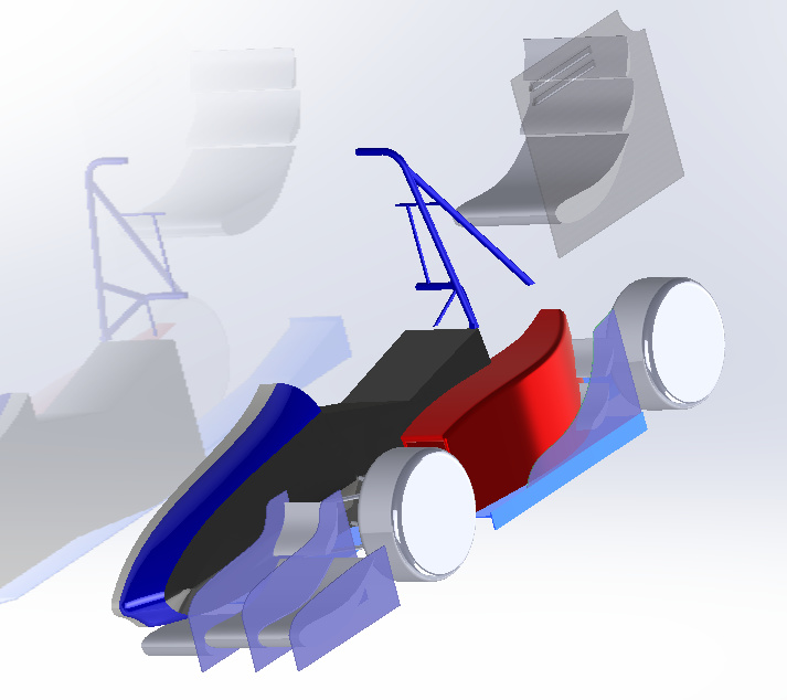
I personally prefer to use a whole car and let the background mesh split the geometry. Having a full car will prevent the mesh from trying to slip through any gaps in between the plane of symmetry and the vehicle.
Also, I would increase the volume mesh in the x direction; add about two extra car lengths at the front, and 6 to the back. You can have have a bigger cell size further away from the car in order to limit the cell count and there the gradients should be lower.
Other than that, if you follow the FSAE Workshop, you should be OK.
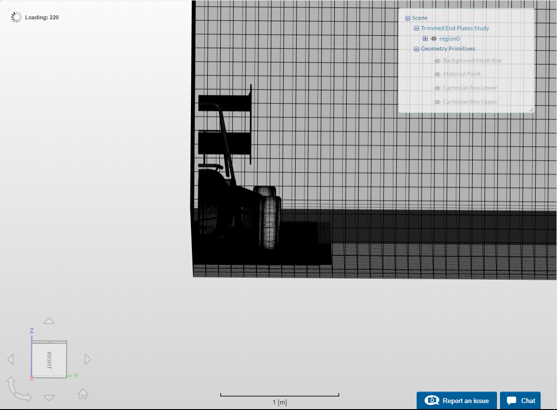
I had to increase the distance from the model to the symmetry plane, because when I would generate my mesh the mesh generator would remove the vertical wall, and then create a mesh inside of the shell of the nose cone. Why was this happening?
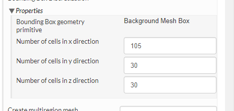
This setting dictates the number of cells over the entire length in X, Y or Z of the bounding box or computational space. For example if your X distance is say 5m and you want a general cell size of 0.1m then you will need to divide 5/0.1 which will require you to the number of cells in the x direction to 50. This is applicable to all cases.
I don’t really have an answer as to why this is happening. In any case, the safest solution would be to upload the full car geometry and let the background mesh do the splitting. Or you could try moving the symmetry plane about 1 mm towards the car so that it intersects cleanly with the geometry (might be a perfect overlap between symmetry plane an geometry that’s causing you trouble).
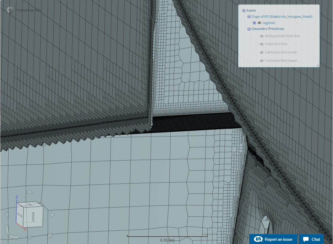
I did try that with the full car in the mesh: “R6 Full Car Fixed Origin”
Half of the geometry ended up being missing after the mesh was created. and holes were created in the geometry.