CFD FSAE Project - Yaw Study Simulation Error

Hello!

I am from a Formula SAE team. Recently, I have tried to perform a Yaw Study. I coped the simulation I had working at 0 degrees. When I tried to change the velocity of the air, all of a sudden all of the simulations are failing. I have tried to decrease the cell density of the mesh, and it is still failing.

Does anyone have any suggestions?

Here is the link: https://www.simscale.com/workbench/?pid=467793078620834649#tab_0-0

Thank you!

Morgan McCann

Hi Morgan!

Looking at the mesh I saw that there are some illegal cells in it and the domain seems to be a bit too small in the front and the mesh too coarse (at least for the big domain). I ran a mesh. I will get back to you as soon as I got better results and managed to get some good output.

Cheers and all the best!

Jousef

Hi Morgan,

Looking at your simulation, I suspect that the boundary condition may be causing the possible errors. In particular, the assignment of the sides. I suggest setting bounding box 2 as a pressure outlet (instead of symmetry) and bounding box 1 as a velocity inlet (instead of a wall) that is representative of your yaw similarly to what you have done for the inlet.

Do let me know how it goes.

Cheers!

Regards,
Barry

Good morning @Get_Barried,

I am assuming that Bounding Box 1 & 4 will be inlets, and 2 & 3 will be outlets?
I guess thinking logically about how a vehicle behaves in Yaw, that would make more sense.

Also, oen of the reasons I am confused about this simulation is regarding this project (SimScale). This project was copied and modified to make the Yaw Study.

A while ago I made the simulation “Jackson W/Driver & Enginer 90000 Sec” under “Jackson Air Density W/Driver & Engine (No Potential Flows)” (11 from the top). This simulation finished to 100%, however when I try to run it the same simulation again it fails. This simulation was performed before the option to use 96 cores was available (I’m pretty sure), when that got added did the maximum memory allowed for 32 cores get shrunk? Or did something get changed when I copied the simulation? The test run of the same simulation is called “Test run - See if settings Changed” under “Test Copy of Jackson Air Density Study W/ Driver & Engine (No potential Flows)”

Thank for the help,

Morgan McCann

Update: The new simulation has failed 33 minutes in, with this error message: 'mpirun noticed that process rank 1 with PID 154 on node exited on signal 15 (Terminated)."

Hi Morgan,

That is correct.

Yes they have recently reduced the storage amount for 32 cores and any mesh more than around 35 mil nodes will not run.

The error is likely due to duplicate boundary conditions. Do remove this BC for bounding box 1 stated below and try again.

Cheers.

Regards,
Barry

@Get_Barried,

Oh wow, that makes sense. I should have checked that, sorry!
I have started another simulation, and will update this post with the results as they become available.

Thank you very much,

Morgan McCann

1 Like

Hello @Get_Barried,

The simulation has errored out at 28 minutes with this error:
“mpirun noticed that process rank 0 with PID 156 on node exited on signal 15 (Terminated).”

Hi Morgan,

So looking at the residual plots, it seems like your simulation is hitting instability for some reason. You can try to set the no of non-orthogonal correctors to 2 under numerics and see if it can be stable. I wouldn’t expect your simulation to become stable however, but lets try that first.

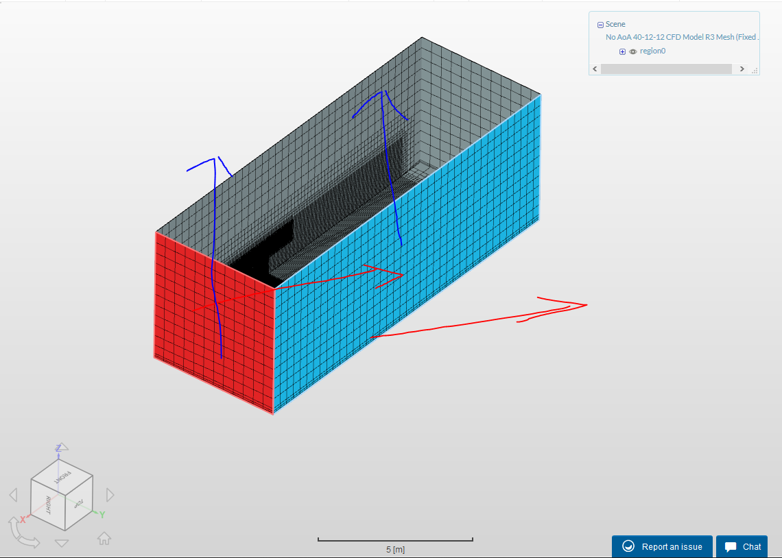
A quick question, isn’t your inlet for the y direction supposed to be -ve instead of +ve? With how you’ve set it up now the flow would flow in the direction of the red arrows instead of the blue arrows and sort of not really interact with the model? Do check up on this.

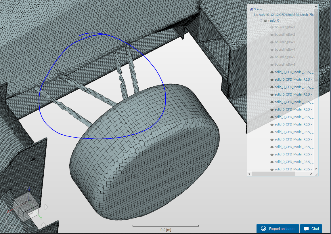
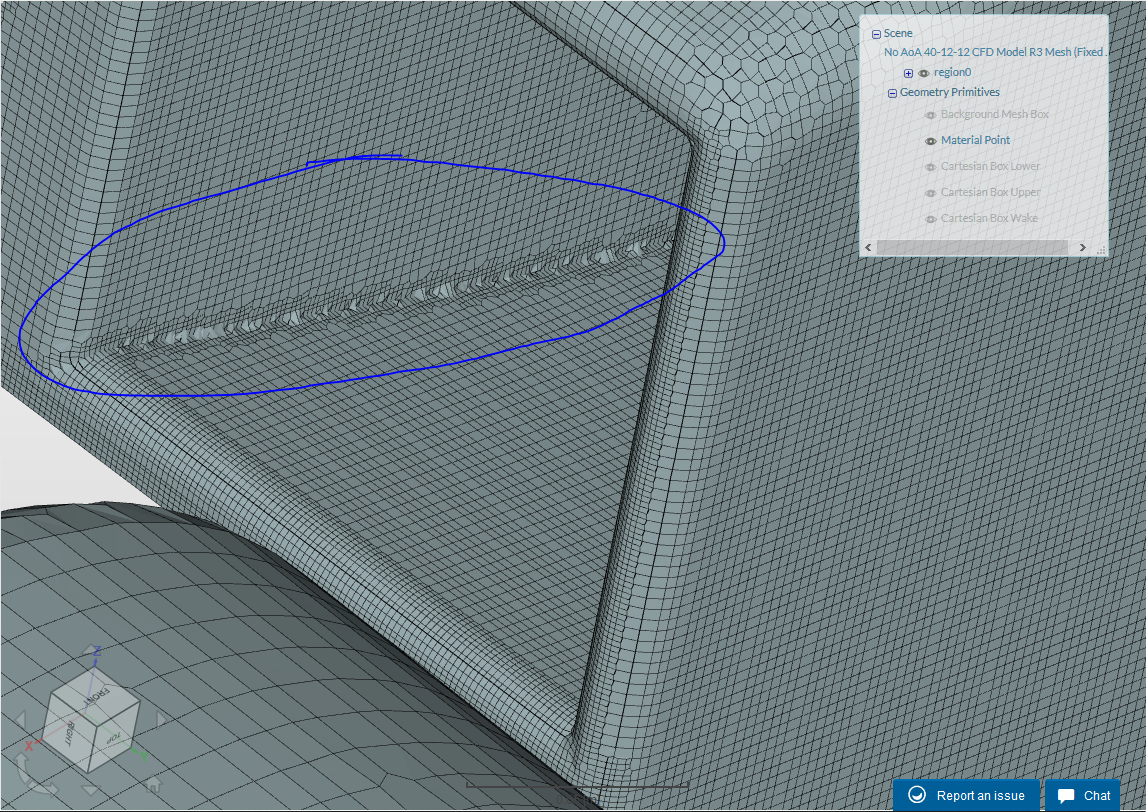
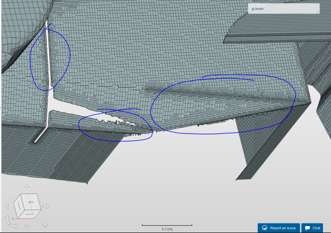
The source of instability would otherwise be the mesh. The current mesh you are using has over 192 illegal faces and this may be the problem. You can refer to this post on reducing the cells but as seen in the figure below, the wheel and wishbone may have insufficient refinement levels along with the interior of the sidepods as well. The last figure shows the connections between the chassis when the floor and sidepods are hidden. As you can see, these areas may cause the illegal cells. An increase in refinement levels should resolve these issues. Do note that you do not need 50 mil nodes or anywhere near that like you previously did for mesh “CFD Model R3 Mesh 2”.

Hope this helps.

Cheers.

Regards,
Barry

1 Like

Good morning @Get_Barried,

Thank you for the help!
I have corrected the inlet velocity mistake, as I had forgotten a negative.
I was looking at how the mesh was created for the wheels, and I found out that somehow I managed to not selected the wheels or A-Arms in the mesh refinement. I will be generating a new mesh with the wheels added along with following the guide you shared.

I had stated to try that guide last week, however I didn’t change my numbers to it fully. I took the average of what my settings were, and the guide. That resulted in a mesh with a few more illegal faces. I will update this with the results of the new mesh and new simulation.

Have a great day!

Morgan McCann

2 Likes

Good afternoon @Get_Barried,

I have created a new simulation and mesh.
I have reduced the illegal cell count down to 99, however the simulation still fails.

I have tried to increase the mesh refinement in the sidepod area, however when I try to do that the mesh fails.

Thank you!

Morgan McCann

Hi @mmccann,

Everything seems alright and well setup in general. Can you try to simulate for a simple forward direction instead of a yaw to see if the simulation can proceed after 2s for the new mesh you just made? Lets try to isolate the problem.

Cheers.

Regards,
Barry

Good morning @Get_Barried,

I have created a simulation in no yaw, and it did fail. (It got to 3 seconds instead of 2 :confetti_ball:)
I noticed that one my directions were wrong on the moving floor, and I fixed that. I created a new simulation, and that also failed. I’m assuming this means the mesh has errors and needs to be fixed?

Thank you for your help!

Morgan McCann

Hi @mmccann,

I guess its time to pop the champagne :joy:.

Yes it would not be an unreasonable assumption. Then again, the no of illegal cells is down significantly compared to the other case. Its hard to tell and moving on from here I would recommend maybe going back to the source file and after some quick checking and cleanup, upload it as an IGES/STEP or Solidworks part format then re-meshing again.

Cheers.

Regards,
Barry

Hello @Get_Barried,

Importing the file into SimScale was one of the hardest parts I have encountered in SimScale. If I use anything but an STL, SimScale will not mesh correctly, or not allow me to click the individual parts. To get the model into SimScale, I currently have to export it as an STL, and then open it in MeshMixer to split the STL into different parts. If I do not do that last step, it comes into SimScale as one solid and I cannot click any individual parts, only the whole car. Perhaps this is where some of the error is coming from?

Please see this link for more info about how I found out I needed to use MixMesher to do this: Geometry Disappearing when Meshing - #24 by pfernandez

Thank you!

  • Morgan

Hi @mmccann,

My experience is opposite of yours where the surfaces are more defined and already split when in either STEP, IGES or Solidworks part files. I always had problems with STL files as they tend to not be very cooperative at least in my case. Do you have the original geometry and what software did you use to draft it?

Cheers.

Regards,
Barry

Good morning @Get_Barried,

I have created the parts in Solidworks. It is an assembly. I think the issue might be the size of the file, also.

I have all of the original geometry, and i could send it to you if you would like.

Have a great day!

Hi @mmccann,

Can you export that Solidworks file as single solidworks file and upload it to your project and try re-meshing? Or have you done it before and it gave you issues?

Cheers.

Regards,
Barry

@Get_Barried,

I remember that I have tried it in the past. I don’t remember why I couldn’t do it. It was either the file size, or it would only display one part instead of the whole assembly (assembly saved as a part, and would open in SW as the whole car).

I can try it again. Is there any workaround for filesize?

Thank you!

Hi @mmccann,

You can try downsizing it and rescaling it here in SimScale to possibly save file size.

If you’re still having issues I can try to see what I can do on my end but will need the source file.

Cheers.

Regards,
Barry