Hi @lisandromaders I’d like to add a few words to this discussion.
Well, for me such problems are nothing new and given my experience I would recommend:
1. Check geometry in your CAD program – I know, it’s obvious, but to be absolutely sure your model is clean do double check, which is:
- create your geometry (whatever it is)
- export it to .step file (or any other)
- reimport it by your CAD system and check if everything is ok; what’s more, import assembly as a part file (!) as in CFD we need a coherent volumes without zero thicknesses
- export again to the same file format
- import to SimScale
2. Remember to place Material Point in sensible location.
3. Now setting mesh setup try to focus on features yourself – don’t leave everything to the program.
4. Further, try to use Surface Refinement instead of Edge Refinement. Why? Because Surface Refinement is focused on surface mapping while Edge Refinement refers to edges length.
I know it may sound funny (strange), rough or even patronising, but this is my way and it works (mostly ![]() ). Sometimes when you work with really complicated surfaces your CAD software may be unable to transfer sophisticated shape to different format. – It can even be unable to reimport properly what it exported (!). Bare it in mind.
). Sometimes when you work with really complicated surfaces your CAD software may be unable to transfer sophisticated shape to different format. – It can even be unable to reimport properly what it exported (!). Bare it in mind.
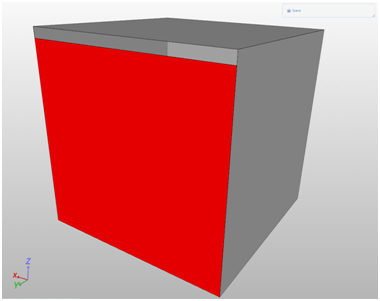
In such situations your geometry imported to SimScale Mesh Creator may contain holes (cracks at the edges). It is still possible to mesh such geometry, but you have to increase toleration factor for mesher mapping. I can’t find such feature here, but the thing is you have to “tell” the mesher it should ignore elements (features, holes, cracks ets. everything) that is smaller than size you set. Therefore, if you use Edge Refinement (which I guess you set at the higher level than Surface Refinement) program will try to identify all edges that fit to this size (in practice really small / short edges) and will try to mesh them. And if the smallest (the shortest) edge for level refinement you set is shorter than the gap between two surfaces, than interior will be flooded. Below you have a very simple example:
INVALID GEOMETRY (box dimensions 100x100x100 [mm] | gap size 5 [mm])
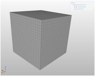
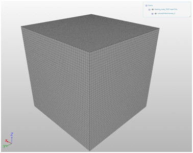
PROPERLY DONE MESH - DOMAIN
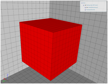
PROPERLY DONE MESH – BOX
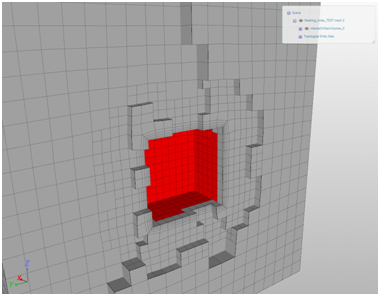
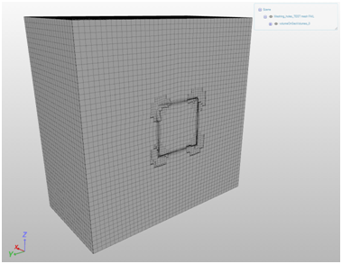
PROPERLY DONE MESH – CUT
IMPROPERLY DONE MESH – DOMAIN
IMPROPERLY DONE MESH – BOX

IMPROPERLY DONE MESH – CUT
Naturally both meshes based on the same input geometry.