Airship FEA :(

I have started a new public project that I need some help on to kickstart me into the FEA world.

I am trying to apply some FEA methods to an airship envelope.

This envelope is symmetrical front to back so I have only drawn the front half of the envelope and will use a symmetry plane (I used a 1/2 space geometry primitive in an effort to accomplish this).

The envelope is made out of 76 micron PET plastic film.

I would like to analyze envelope shape and stresses with 3.5x10⁻⁴ MPa gauge pressure inside it using air, helium and hydrogen as the internal gas (air at sea level STP will be the gas outside the envelope).

Ultimately, I am hoping that there will be a way to account for the shape and stresses in the fabric that takes into account the helium, hydrogen or hot air lift and even the weight of the fabric itself. I assume I will need to add a bridle over the envelope and attach the bridle to the ground somehow.

But first I just want to pressurize it with air to see the shape and stresses in it as just an inflated structure.

I have been able to create a mesh using default parameter values.

My simulation ‘Run 1’ did not finish and I do not understand the error.

I am not even sure I have set the simulation up correctly.

Once I get a simulation to finish without error I will have more questions to accomplish my ultimate goals.

Any help would be appreciated…

Thanks,
Dale

1 Like

Hi @DaleKramer,
very interesting project!
I fear it is beyond what we can currently solve - but I’ll definitely help to push this as much forward as we can with the current capabilities.

First, let’s talk about the original error you had.
In your analysis you had only defined a pressure BC and no constraint - this is not sufficient for a static analysis. The system needs to be statically defined - in a sense that there are no rigid body movements possible.
To realize this, I added a symmetry condition (which constraints X-displacement - and implicitly also rotations around Y and Z). To constrain the remaining 3 rigid body movements, I added a deformable remote displacement at the nose which constraints Y- and Z-movement as well as X-rotation.

Still the simulation did not converge - which brings us to the actual problem with the application: you are trying to model a VERY thin material with 3D linear tetrahedral elements - which is never a good idea. It will generate elements with a very high aspect ratio which leads to numerical difficulties at least and then also to inaccurate results. Usually one would consider shell elements starting at a ratio of thickness to length of about 1:20 - here we are at about 1:50000 (for the symmetric model).

To solve the numerical issues I had to extremely loosen the quality criteria of the solver (deactivate the residual check by defining a threshold of -1) and then at least the linear system could be solved:

You can also check the model setup in detail here.

Now, to actually model the application accurately you would need a number of changes and features which are partly not available on SimScale:

  • for modelling such thin members you would need to at least need Shell elements, probably even Membrane elements (which have no bending stiffness) would be needed to model the behavior of a real “fabric” realistically.
  • if the pressure will deform the membrane significantly you would need to run a nonlinear analysis and use a follower pressure BC such that the element normal (and with them the pressure direction) is updated with the deformed geometry during the computation.

The nonlinear static analysis and follower pressure are available, but there is nothing here to model the “fabric” material correctly. You might get with a very good second order mesh a somewhat qualitatively “reasonable” result - but the mesh size would explode to several million nodes (it already has 730K nodes).

This is just an initial evaluation, but you might want to consider some of the concerns.

Best,
Richard

4 Likes

Thanks Richard, your reply is awesome!

I am afraid I can not address all of what you are trying to portray to me without asking some things in a series of questions.

For now:

  1. I do not think that the X location of the nose faces should be constrained. In a copy of your project, I removed the X constraint on your ‘Remote displacement 3’ constraint and the sim run finished without error. Is my edit not a more realistic constraint setup (Not quite sure how my edit constrains X rotation though)? Also, I guess I incorrectly assumed that the Half space geometry primitive would have automatically constrained all faces that fell on its plane).

  2. Why would there need to be a distinction between a normal geometry, a shell geometry and a fabric geometry? I think I can calculate the fabric stress and strain using normal calculations of the PET material parameters so why can’t the FEA code do so? For instance I can take a one inch with piece of the PET fabric, load it and calculate the stress and strain in the elastic region easily and have it match the real measured stress and strain. None of my individual mesh triangles exceed 30:1 (I am sure I can reduce that) so why does FEA care about how thin the material is?

I will try 2nd order mesh and nonlinear analysis too after I get my brain wrapped around your answers.

Dale

Hi @DaleKramer,
no need to run 2nd order case - I already finished that!

You see the results are already quite different - displacements almost 1000 times higher!

No time now, but I will comment on your remarks later.

Here is the link to the 2nd order case: https://www.simscale.com/workbench/?pid=4685378159218892315&mi=run%3A1%2Csimulation%3A5&mt=SIMULATION_RUN

Best,
Richard

2 Likes

Hi @DaleKramer,
now to your remarks.

  1. I actually did not constrain the X-movement of the nose, just the X-rotation and the Y- and Z-movement.

We can also see in the results when we only plot the x-movement that there actually was a contraction of the model in X-direction and that the nose moved:

  1. It is because of the specific microstructure of the fabric that makes it behave quite unisotropic and totally different in tension and compression - you can not model this with a linear elastic material and solid elements with no specified orientation. This is of course a general statement - in your specific case it might be possible to get realistic results even with the current modelling (for example since in your model there is no region in compression) , but I won’t bet on that right now. FEA does care about thin materials because of the underlying modelling assumptions that are made. If you for example use a linear element it can only represent a constant stress in the element and not a linear stress distribution across the thickness as you would get in a bending scenario and this you get a much stiffer result as in reality - this is known as “shear locking”. Shell elements have by their formulation an assumption that the stresses vary linearly across their thickness (of course there might be different kinds of shells where this can also be different) - so they can easily represent the linear stress distribution across the thickness for pure bending. The accuracy of the element integration in FEA is also dependent on the element quality and the more the element differs from the “ideal element” - a perfect tetrahedral in our case - the worse the approximation due to numerical integration is. I guess you know of similar effects that result from bad quality elements in the Finite Volume Method for CFD applications.

Best,
Richard

2 Likes

Thanks.

The 2nd order shape is not realistic (especially at that pressure).

Here is the envelope partially inflated with almost zero gauge pressure in it. Any pressure in it is due to the weight of the envelope material itself (excuse the seam wrinkles, it was sealed by hand):

I would love to be able have FEA show me this shape at this pressure. The bottom of the envelope is flat on the floor.

I have never seen an envelope billow between the seams like the 2nd order shape, even at high pressures.

I will investigate whether the uneven bumps are caused by the precision on my Rhino cad model. I will increase precision and see if it is smoother.

Dale

2 Likes

Hi @DaleKramer,
I also wouldn’t have expected the results to be realistic :wink:

Definitely the deformations are too high to use a linear analysis without follower pressure, so you would need to change to that - which would mean 45min per iteration at about 2-5 iterations per step and maybe 2-5 nonlinear sub-steps would lead to a total computation time of 4 * 45min =180min to 25 * 45min = 1125min on 64 Cores (using an iterative solver might reduce that though).

Also I think the “bumps” are more due to the meshing and anisotropic mesh distribution.

Best,
Richard

1 Like

Sorry, somehow I missed that.

RE: 2. If the envelope material were actually a fabric with threads I would understand your concerns. But this material is homogeneous PET with a very thin layer of aluminum vacuum deposited onto it (I am ignoring the aluminum for stress/strain calculations). I believe this envelope ‘fabric’ can be treated as completely under tension once the envelope has enough pressure in it and it is not laying on the floor. Under these assumptions, wouldn’t the nonlinear static analysis and follower pressure simulation be close to realistic?

Dale

1 Like

I started over with the CAD model, this time I made a left/right symmetry plane and I am using only a 1/4 envelope shape and I increased my CAD file precision to 5e-07 meters, that should be fine enough to take any precision concerns away (it was 5e-05 meters on the original model).

I created a new project for this and the ‘Static 1 Nonlinear’ simulation with following pressure which I am trying to run.

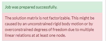
Unfortunately I can not understand why the simulation error seems to think I have not properly constrained this new model geometry, can someone have a look? Here is the error for ‘Run 1’:
constraints

Also, I added gravity to the sim setup in the ‘Model’ parameter. I think I have done that correctly but I can find no information in the Docs about when to use Linear vs Nonlinear Gravity, can you enlighten me?

It also seems strange that the default valued 1/4 envelope mesh is 1.6M cells vs the 1/2 envelopes 0.7M cells, is this strange or is it due to some meshing defaults different between static and dynamic simulations?

Again sorry for having problems with these basic issues…

Dale

Hi all,

I really need to continue working on airship envelope stresses and in determining expanded shapes under inflation pressure.

Does anyone have any ideas on how to start here?

I even want to be able to, for instance, create a simulation that models how the envelope deforms and how its internal stresses are affected when I throw a ‘rope’ over the top of the envelope and then tie the ends of the rope together, below the envelope, and gradually put a load on the rope.

If I can’t even get the envelope to inflate properly I will never get to the end :wink:

How about it any Power users

Thanks,
Dale

EDIT 4/13/2019: Now I have inadvertently changed my current settings for the Run 1 error in Post 9 so until there is a way to recall the state of a failed simulation run back to the forefront there seems to be no way to return to this project and debug it without a painful and tedious transfer of Run 1 settings back to the sims current settings (I think that might do it but not on my list right now) :frowning: :frowning: :frowning:

Very late response from my side here Dale.

That’s a pity… did you not create a duplicate of the simulation beforehand? But I get the point here that it would be way more convenient to have some adapted workflow and maybe some “memory” that CTRL+Z’s your settings in a specific manner. @StevenGu, do we have anything like this in planning?

Best,

Jousef

Actually I am not sure what setting I changed but surely I did not expect to end up where I got to, if so i would have made that duplicate…