Air inside high speed rotating drum

I’ve very new to CFD (I’m an Electrical Engineer), so maybe some questions I ask are a bit premature
and I’d discover them myself working through the tutorials, so I’m a bit wary of asking,
but my enthusiasm is now, so I’ll ask anyway. I have commenced SimScale Academy
and bought Batchelor’s Introduction to Fluid Dynamics, so hopefully will catch up soon.

Ultimately I’m Looking to simulate a rotating solar collector as summarized here… https://tinyurl.com/rotatingsolar1 with more detail in the original thesis… https://www.builditsolar.com/Experimental/RSB/The_RSB.pdf

I’m thinking the Conjugate Heat Transfer might be a good fit (after I finish the webinar on that)
to cover heat dissipation to the environment, but in the meantime I’m trying a simpler system
without heat transfer. The original project only ran at modest rpm, but I want to understand the pressure stratification at high rpm - and later with low pressures of the order of 1 Pa.

So here is my simpler project for simulating air in a rotating cylinder as a Laminar Steady-State Compressible Gas with a MRF Rotating Zone applying the rotation.

Run2 @ 100rad/s does produce some pressure stratification as expected
image

But I wonder if the pressure may be different in the center, so I add a cutting plane and get…
image

which doesn’t show the pressure profile in the middle plane. So…

Q1. How can I show the pressure gradient in the middle plane? 

Now even though the solution ends up physically plausible, the residuals are poor…


Now I have to admit, I don’t know what all these specific residuals are. “Ux/y/z” is straight forward, but I’m only presuming “p” is pressure and “h” I have no idea, and my google-fu is failing me. So…

Q2. Where can I read about the meanings of the residuals? 

Just changing the speed with Run 3 at 1000rad/s seems to produce a better result with more stratification…
image

and better looking residuals…

but I don’t know the significance of the “p” rising after the minima near 100s. How might it be interpreted? (Q3)

And maxing out the speed with Run 4 at 10000rad/s seems broken - the stratification is lost and the negative pressure seems implausible…
image

and the velocity residuals oscillate badly…

so its easy to guess I’ve exceeded the bounds of the solver, but I’d really like to get a sim to work at this speed.
There exist real-life turbines that spin at this speed, and this plays into other ideas I want to investigate.
So rather than thrash around burning compute time I thought I’d just ask…

Q3. I imagine that at that high speed, a finer time resolution might be appropriate before making the mesh smaller?

Q4.  Is a laminar flow suitable for this?

Q5. Are No-slip walls correct?    I've since read that No-slip is for viscous fluids which stick to the wall, which doesn't sound like gas.

Q6. I'd like to re-do exactly Run3 by change it from No-slip to Slip, but I've lost track of several setting changed a few days ago?   Now because I'm lazy, how to I copy the archived-Run3-settings to the current-settings so I only need to make that single change before the the next run?

Cheers, Ben

Hi @bcoman,

Your simulation domain is limited to that volume:

, hence you have nothing inside your ‘drum’ and ‘middle plan’ shows what it should, in your case.

Do not exceed 0.3 Mach for air velocity with steady state simulation (you are at 500 m/s with your 10000 rad/s.

Q3: no, in stead state simulation you have steps (called seconds) and those seconds have no physical meaning.
Q4: For slow velocities, laminar is OK
Q5: Walls should be no-slip. Gas really ‘sticks’ to walls in our galaxy.
Q6: Make a copy of previous simulation to preserve setting.

Cheers,

Retsam

1 Like

Thanks @retsam, I’ve been offline a few days. And then was a bit slow catching on why I had nothing inside my drum until I went back and re-did the second introduction tutorial and got to understand what the internal mesh should have looked like…

So then I saw my error… I had been confused that Air filled the internal volume since it said so here…

when actually I’ve ended up with air inside the “skin” of the drum, which isn’t what I wanted.
What wasn’t apparent to me before is the geometry says “6 faces”, which I now presume is 3 outer faces and 3 inner faces.
image

The Introducing Flow Volume Extraction video showed me how to create a “Closed Inner Region”…

after which having only 3 faces seems better…

and the mesh generated looks more like what I wanted…

Simulation is running now.

1 Like

Now, as you have two solids, one (Rotating Volume) should be defined before meshing as ‘Cell zones’ (Mesh > Cell Zones). If not, Simulation will break with ‘A multi-region mesh was assigned - this analysis-type requires a single-region mesh.’ message.

For MRF zone, you need to define rotation speed (rad/sec).

Take care,

Retsam

2 Likes

Yes, I was running into that message " A multi-region mesh was assigned - this analysis-type requires a single-region mesh". After trawling other posts last night for an answer, I came back to ask now and you’ve already provided one answer. Thanks @Retsam.

After adding a Cell Zone to my “Compressible 2 - two parts” sim, I have a new error message “One or more cell zones are adjacent to a flow region cavity. Cell zones faces must be inside the flow region.”

I read here that " The rotating zone volume should be 100% solid and should intersect with the flow volume (think of the rotating zone volume as a plain, 100% solid part)."

but perhaps my “Rotating Volume” is a surface not a solid?


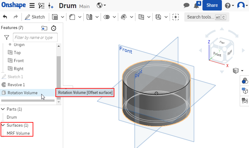
Was it misleading of me to name it a Rotating “Volume” ? (I’m not familiar with naming conventions).

I’ve found " B) CONVERT THE SURFACE INTO A SOLID" in the knowledge base article “How to Create a Rotating Zone”, so I’ll try that next.

I tried half a dozen more ways with no luck.

The last one “Compressible 10 - Outer volume 1st” was trying two volumes created in OnShape as separate “parts”. Here is a section view half way along cylinder…

Bu the same error message occurs…

  • One or more cell zones are adjacent to a flow region cavity. Cell zones faces must be inside the flow region .
    .

Project Link: SimScale

btw. I should actually confirm… I’ve had success making the Rotation Zone identical to the “Air” volume, but I read somewhere that its beneficial to make the Rotation Zone slightly larger than the flow volume, so that is what I’m trying to do.

Hi @bcoman,

I confirm as well that MRF could be bigger then ‘simulation domain’, at least it was that way in 2019. Please look at all my explanations in that small and handy project: Internal CFD with MRF .

The way of defining Cell zones is now different and possibly other tests are done on meshed volumes. Need to think for a short while on that limitation…

Well, I did that simulation (inspired by your very first test, which was suspect to me, at first glance), but did not set a cell zone this time.

  • I used 1 solid (cylinder 0.1 x 0.1 m). This is my simulation domain, hence simply air volume.
  • I used very rough standard mesh (4), but without cell zones.
  • I switched off ‘Hex element core’.
  • In Boundary conditions I defined three faces as no-slip.
  • I used k-omega-STT simulation type.
  • In Simulation control, I did set ‘Potential Foam initialisation’.
  • I defined MRF as being that one solid (cylinder), rotating with 62.832 rad/sec.
  • Meshing took 0 core-hours, 200 step simulation 0.1 core-hours.

Here is the result:

It may be correct, however you would need to make better mesh, I guess.

Cheers,

Retsam

2 Likes