Question
In CFD simulations, can users model wall roughness? If so, how is it done?
Solution
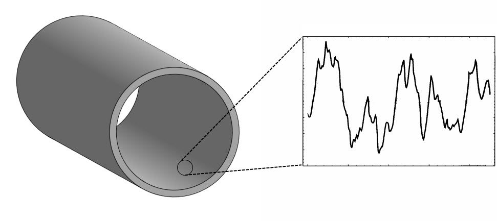
The surfaces of all materials used in engineering applications are rough. Levels of roughness can vary based on material, mechanical finishing, and polishing, amongst others.
By default, SimScale considers walls to be smooth. In applications where the wall roughness is considered important, it can be accounted for via custom boundary conditions in the OpenFOAM®-based solvers and directly via the wall boundary condition in the Subsonic solver.
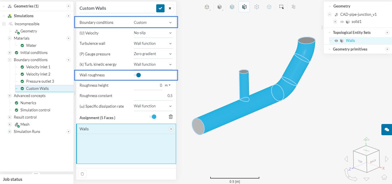
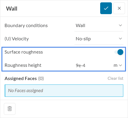
After enabling wall roughness, the user has to input two parameters: roughness height and/or roughness constant.
Roughness height (Ks)
This parameter is a representative distance to the wall. Therefore, a value of 0 results in smooth surfaces. A sand-grain type of roughness is assumed.
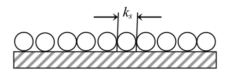
As shown above, when the sand-grain roughness is uniform, ks is easy to obtain. For irregular grain sizes, the user can specify ks based on average values.
In some cases, the wall roughness will be very irregular and won’t be similar to a sand-grain type. In this situation, users should estimate the equivalent sand-grain roughness.
Some authors explore correlations between measured surface roughness and equivalent sand grain roughness (Adams and Watson, 2012). It’s also possible to find estimates based on the material of the wall.
Note
Average roughness height for different standard industrial materials can be found on many online platforms like The Engineering ToolBox.
Roughness constant
Roughness constant is a parameter that measures how uniform the roughness is. Inputs may range from 0.5 to 1:
- 0.5 indicates a uniform wall roughness;
- 1 means that the roughness is strongly non-uniform, both in terms of spacing and height.
Note
When wall roughness is enabled, it causes changes in the near-wall velocity profiles. SimScale accounts for these changes by modifying the wall functions used in the simulation.
For this reason, wall roughness is only available for k-epsilon, k-omega, and k-omega SST turbulence models. Furthermore, it’s not supported for the full resolution wall treatment.
References
References
- Ladouceur, F., Poladian, L. Surface roughness and backscattering. Optics Letters, 1996.
- Hetsroni et al. Micro-Channels: Reality and Myth. Journal of Fluid Engineering. 2011.
- Adams, C. G. T., Watson, H. A Simple Algorithm to Relate Measured Surface Roughness to Equivalent Sand-grain Roughness. International Journal of Mechanical Engineering and Mechatronics. 2012.
- https://www.engineeringtoolbox.com/surface-roughness-ventilation-ducts
Note
If none of the above suggestions solved your problem, then please post the issue on our forum or contact us.