I am designing a car as part of a school project, the aim being to reduce the drag as much as possible and maximize downforce. I have completed a design in Autodesk Alias and exported it as a STEP file. After many failed attempts, (at first due to a faulty mesh, then due to the simulation being too resource intensive for a free account) I managed to complete a simulation. I tried to use this tutorial to help me. I had previously ran successful simulation, but the were much simpler. This latest run completed, but the result is very strange. There isn’t much to explain that wouldn’t be easier to see for yourself: https://www.simscale.com/projects/BrunoI/epq_2/
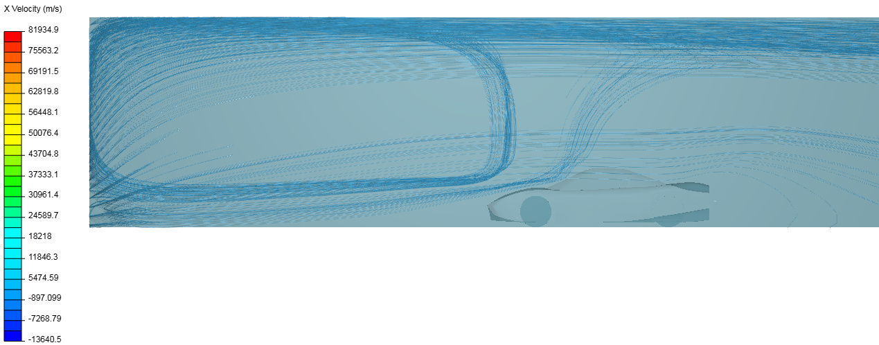
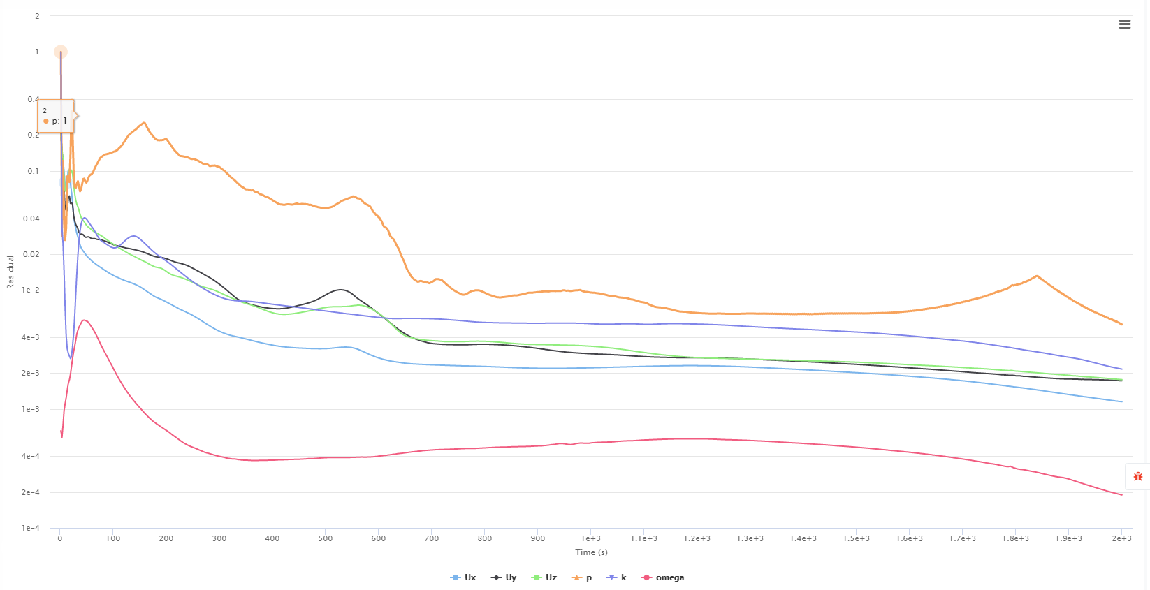
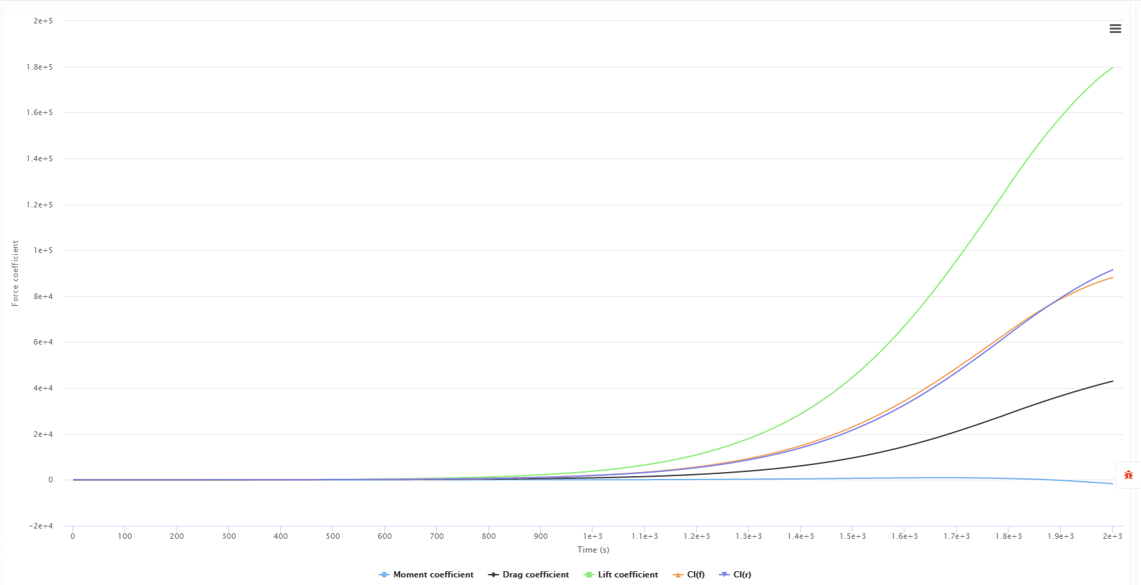
There is strange behavior in the convergence plot, forces and moments graph, forces and moments coefficients graph, and If you look at the particle traces they seem to be recirculating strangely.
I assigned the wheels as rotating walls, and the air vents beside and behind the windows as pressure outlets to better model the behaviour of the tires and vents. Maybe this is the source of the issues? I also increased the timestep to 2s to reduce simulation time, IDK if this would have such a large effect.
This project is due soon and I have no idea what to do so any help is greatly appreciated.
From SimScale documentation: Moving Wall : This condition is used for Translating surfaces where the tangential velocity component is specified. The normal components are same as Slip condition."
Boundingbox5, I believe’ should not be a moving wall, but No-Slip boundary, (it is your ground). Otherwise all your walls will have ‘Slip’ BC. Perhaps your setup is on purpose that way…
Pressure Outlet should be just the Boundingbox3. Parts of your car cannot have ‘pressure outlet’ boundary conditions. You have three parts of your car with that BC.
As BC is not defined for your car, by default all parts will have ‘no-slip’ BC, so far, so good.
I had assigned those boundary conditions intentionally, the bottom face as a moving wall because it represents the road moving beneath the car, which is what they did in the tutorial too. For the pressure outlets, how else should I simulate air vets? It I made them standard walls they would disrupt the airflow in a way they shouldn’t IRL. I did notice however that in some simulations air flowed ‘into’ the car.
I have run the simulation with Potential foam initialization disabled, since this changed very little I tried again this time with the gradient changed to cell limited gauss linear as suggested in another post with a similar problem. This changed little too however.
Now, your Run 10, has good looking Convergence Plot. You removed those pressure outlets on car, so they were possibly the culprit.
I understand the concept of “Moving wall” having the same velocity as air inflow. Perhaps there is no way of having default ‘no-slip’ BC on that wall, as ‘slip’ BC in such a small distance from car, will have significant influence of Forces and Moments.
One more think: there is now a huge initiale ‘wake’ on “Forces and Moments”. Your car starts to move at 31.3 m/s in a blink, hence the result. You can reduce that wake by making a smooth start using CSV file and progressively energy to the flow for first 50 - 100 steps.
Potential Foam initialization can help with initial stability of simulation. In your case Simulation has to dissipate initial energy and making it ‘natural’ (accelerating the car), will help. Currently your simulation can be stopped around 800 steps (it converged). With CSV smoothing, you can reach convergence in about 400- 500 steps.
Disabling this may help in the stability of the simulation. Sometimes potentialfoam causes the simulation to diverge, why exactly this happens I am unsure.
I just checked your latest run 10, it seems to be fine even if it is a oscillatory convergence. The initial fluctuations may be reduced in numerous ways, the first in enabling potentialfoam, the other is adjusting the numerics and the last is by as was suggested by Retsam, ramping the inlet. However, the fluctuations do not affect the final result only in that they may increase the time needed for the simulation to converge.
Otherwise, post-process your results for run 10 and see if they match what you were expecting, or better yet validate it with some actual data.