I am trying to simulate the response of a structure mounted on a vibrating table. The vibrating table vibrates with a defined amplitude, let’s call it A, in a range of frequencies given by a standard. The problem is that I cannot give the amplitude itself as an input in a harmonic analysis, but I have to give a load. So here comes my approach:
Having the amplitude, A, I calculate the acceleration (peak) given by the formula a=A·(2·pi·f)^2
After that, I apply the secon Newton’s Law: F=m·a
being m the mass of the structure and a the list of accelerations from the previous step
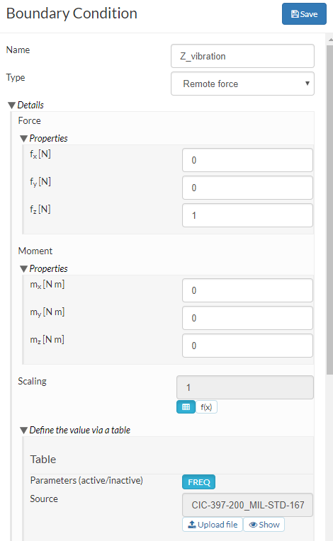
Finally, I apply the load in the base of the strusture as a Remote Force as shown in the figure below with a table obtained by following the explained steps (the remote point is the origin wich is in the center base of the structure)
The problem comes when the response is exaggeratedly exaggereted! The amplitude should be lower than 1mm but it happens to be more than 500 mm!!
Is my approach correct? Did I do something wrong while setting up my BC’s?
Thanks in advance.
Alex
PS. I feel stupid, it seems to be a units issue since I computed accelerations in mm/s2 instead of m/s2. I realised it while I was writing the post, however, I publish it anyway because I forseen that the units won’t be the only issue since this is my very first harmonic analysis…
Hi @alex_roque and sorry for the small delay in my response.
So given the fact that you realized the unit differences is everything clear now or now? For the simulation setup let me tag the more experienced PowerUsers @BenLewis, @cjquijano as well as @ggiraldo here who might give you some tips on your setup. For that please make sure to share your project here
I think that the harmonic analysis is not suitable for this kind of problem (base excitation). This is more like a seismic analysis, which is related but not the same. The reason is the rigid body motion modes and some numerical corrections that the solver has to make in order to get valid results. Someone please correct me if I am wrong.
Other thing I see is that one can not impose displacements on harmonic analysis. I think this should be possible, I know Code Aster has the capabilities. Maybe candidate for a feature request? Other possible improvement to the platform would be the implementation of the Code Aster function DYNA_VIBRA, which would allow to carry more general vibration cases, such as seismic, some non-linearity, even transient response on modal basis, which should be more efficient than time integration. What does @rszoeke think about it?
Thank you very much for your valuable insight. Although I’m sad for your explanation
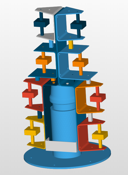
I will share some results with you. Well, first of all, I will describe my case with more detail. My system is shown in the picture below, a stack of marine loudspeakers (represented by the weird “boxes” that represent their weight).
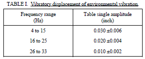
My main concern is to find out wether or not it will resist a vibration test according to the standard MIL-STD-167. The frequency sweep it will be undergoing is the following
To ease the reading: 0.03 inch=0.762 mm — 0.02 inch=0.508 mm — 0.01 inch=0.254
In order to apply the desplacements described in the standard I follow the steps explained in my first post (with the correct units this time…)
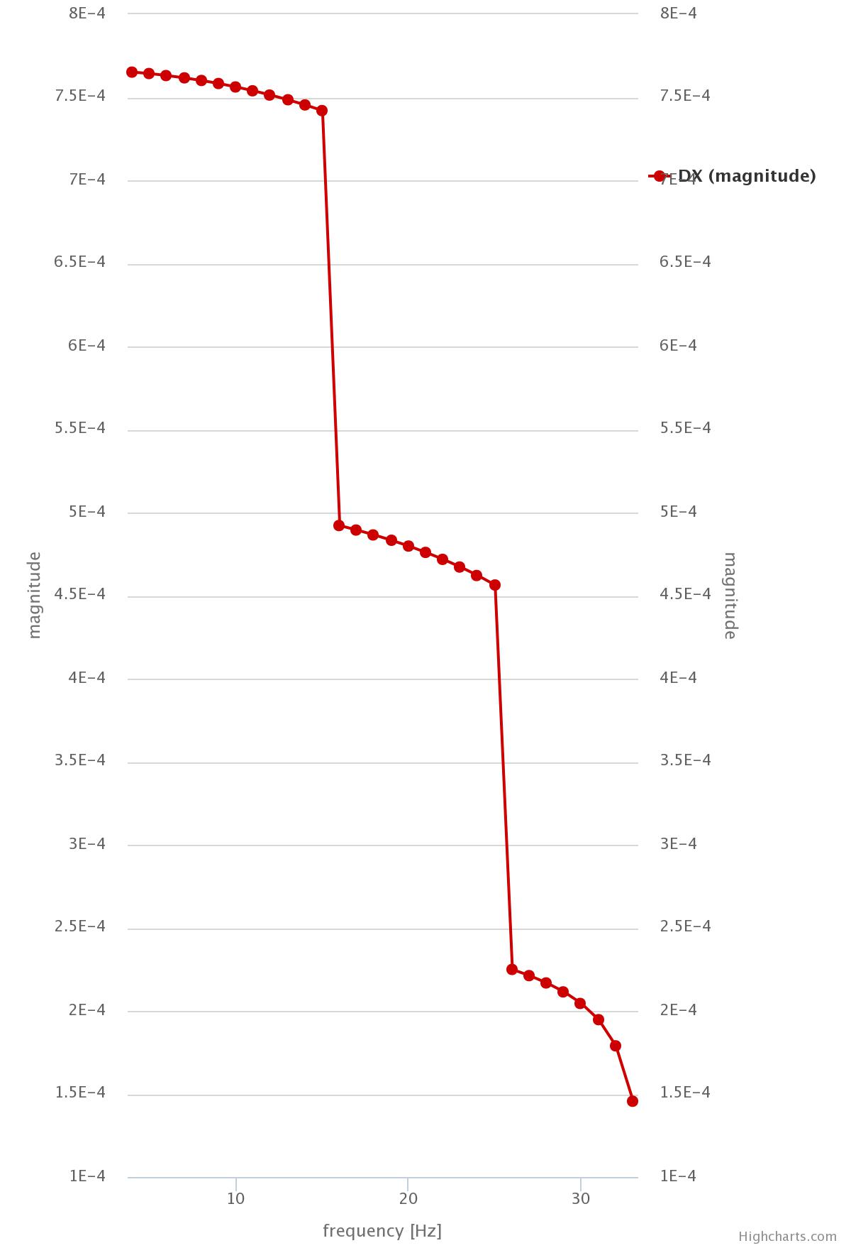
Besides, I use 5 probing points: 1 at each speaker’s mass center and other one in a side of the structure’s base (because the bottom column is hollow) as a control value for the displacements. The last probing point is intended to undergo the excitation as it is, without any distortion or damping. However, I get the displacement chart shown below when it comes to HORIZONTAL excitation (X axis).
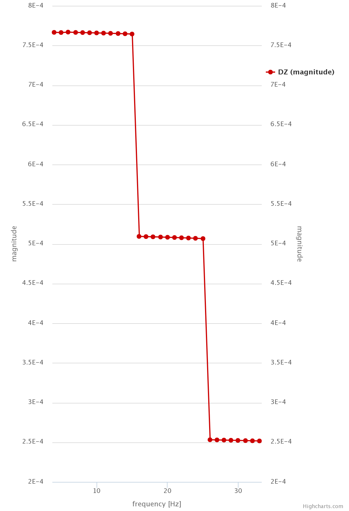
As you can see, the 3 levels of displacement expected are pretty clear, but instead of being flat levels they decrease with the frequency. This is not happening when it comes to VERTICAL excitation.
Here you can see clearly the 3 modes of excitation stated in the standard and the amplitudes obtained are within the limits defined in it. The forces for both cases are extracted from the same table calculated in the same way as it has been already explained. In the begining I had some doubts because my calculation made sense to me for the vertical excitation but I was unsure if the same forces were going to work in the horizontal excitation. However, finally I decided to give it a try since gravity seems not to be taken into account in this kind of analyses. In view of the results, I did something wrong, but I don’t know what.
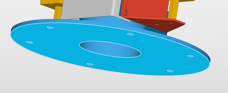
To get a closer look to my case I will share with you the way I defined the base excitation for both cases with a picture so as to ease the understanding of my explanation.
For the vertical excitation I applied the vertical vibratory forces (Z axis) in the lower surface of the circular base, shown in blue in the picture, while I blocked the displacements in the X and Y axes for the cylindrical surface of the base (I was not sure if it was needed or not, but I tried it. I think the results are not affected by this constraint…)
For the side excitation (X and Y axes) I did the opposite. I applied the Remote Force in the side cylindrical face of the base, while blocking the Z and Y (or Z and X) displacements of the lower face of the base (the same as before, not sure if needed but I suspect that it has no effects).
I hope that this explanation of the boundary conditions can help you figure out what I could do wrong and why the results obtained in the base probing point are so different between the vertical and horizontal cases.
Furthermore, I noticed that althought I requested the von Misses stress to be shown as a result, it didnt show up in any of the test I have made so far. Is there a reason why stresses are not given as a result?
I hope you can give me some hint, although @ggiraldo has already stated that my case is supposed not to be calculated for now in SimScale…
Well, I think that your equations for the equivalent force would be valid if such a force would be applied at the center of gravity, but being applied at the base, there are some inertial effects that should be taken into account in order to get correct results.
Hi @alex_roque,
I think you should be able to get reasonable results with this approach - assuming you can get the damping coefficients right.
You did fix the base in Y- and X-, correct? Otherwise you might get some additional rotating behavior instead of a 1-dimensional vibration.
Also, instead of a remote force you can just use a single force laod, this will be computationally more efficient and lead to the same results.
Best,
Richard
I really appreciate your insights! It’s good to know that my approach may be kind of useful, althought maybe not very much accurate as per what @ggiraldo says… However, at the moment I just want to know if there’s a weak point in the structure which is easily and quickly solvable, which is not easy when stress field is not given out as a result! Do you guys know why is it happening? I only get displacement and acceleration fields and the charts with the probing displacements I set up in the Point Data field.
@rszoeke: As per the damping coefficients, at the moment I am not accounting for damping effects since I don’t know exactly how to get the correct coefficient values. Could you help me with that? Any paper or something where I could find a way to define the damping coeffs.? The materials of the structure are aluminum and steel. And yes, I fix the base components that are not supposed to move freely.
Alex, is the remote force periodic? If the base is to vibrate, I would expect a sinusoidal input, but your acceleration expression—and therefore also your force expression—are just linear functions of frequency.
This is fine if the SimScale Remote Force model is periodic and all you need is the amplitude of the force signal. Otherwise, it would be a problem (as the force would then cause the frame to accelerate continuously in the same direction, leading to excessive displacements).
By the way, the first plot (for horizontal excitation) is just what I would expect from a body accelerating in a constant direction. The second plot seems right, but then again, you say that you are using a vertical vibratory force, so you wouldn’t run into the same problem here.
Just a thought. I frankly don’t know much about the remote force, so I am going strictly by what you say your acceleration expressions are and what I would expect them to be…
As far as I know once you have chosen Harmonic analysis all loads you give to the solver are treated as periodic loads, and as per the results I get it seems to work like that. The behaviour I get in the horizontal vibration is a litlle weird since amplitude seems to decrease when frequency increases, which I don’t know if it makes sense or not… Maybe it has something to do with what @ggiraldo said, I mean, the fact that in this case the force is not applied to the gravity center, I don’t know… Maybe any expert in vibrations around here can give me the reason why this is happening.
By the way, I still haven’t find the way to obtain the stress field as a result, only the displacements and accelerations but no stress at all. I have tried to get von Misses and Cauchy stress, but none of them have shown up after tha execution of the solver. Any reason why this is happening?
 The amplitude should be lower than 1mm but it happens to be more than 500 mm!!