Hey guys,
I´ve been working on this FSAE car simulation, with the goal to have a estimate number of the Cd and Cl of my car and see the behavior of the airflow in and around the sidepod. I already did a lot of testing with the geometry, which I chose to simplify by only using the truly aerodynamic devices and simplify the rest. The issue I found here is that when I import the geometry, it comes with all the dimensions multiplied by 1000. To solve this, I use the “scaling” tool in order to obtain the geometry with its real size. After this, I tried many different mesh settings to acquire, at my point of view, a good mesh (only 2 illegal cells of 15M and some good boundary layers with y+ estimation of 30 or 50, depending the part of the car). For the initial and boundary conditions, numerics and simulation control, I used the settings that i learned at “Applications of CFD in Formula Student & Formula SAE” workshop at Simscale Academy. I tried three simulation configurations: one without any rotation with inlet of 20 m/s, the second one with MRF and Rotating Walls of 20 m/s and the last with rotations of 15 m/s. The problem is that, in all three the Cd and Cl results were completely unreal and I dont know why. The only reason to this that i see is the “scale” that i mentioned in the beginning, but I can’t test without it, so I´m really stuck here.
Here´s the link to my project: https://www.simscale.com/workbench/?pid=5118982399588585615&mi=spec%3Ae8184e16-2959-4ec4-ba11-de0cfd1afd66%2Cservice%3ASIMULATION%2Cstrategy%3A65%2Crun%3A124&ps=analysis%2FIncompressible--oneOf%2FboundaryConditions%2F0
Thank you all,
Mateus
Hey, @mat_esser,
Some comments about it:
These are the equations used for Cd and Cl in SimScale:
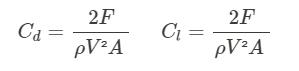
Where F are the forces in the respective drag/lift directions. The parameters V and A are user-defined right here:
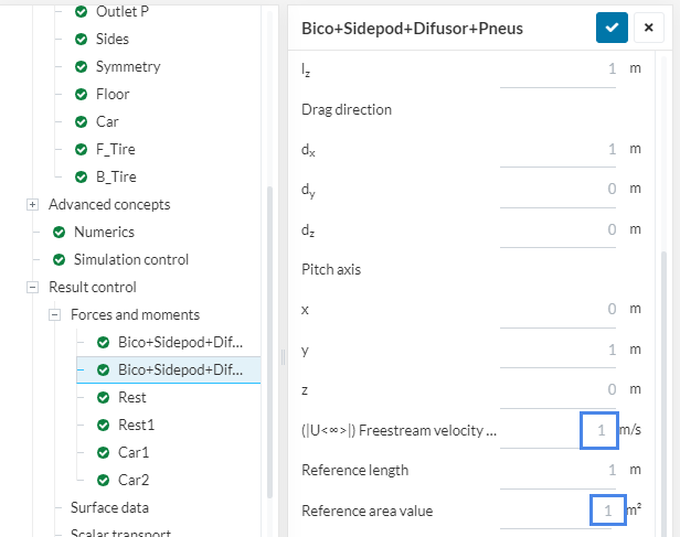
Make sure to input the appropriate values here, otherwise the Cd and Cl results will be all over the place.
In your case, the freestream velocity is pretty straight forward. The reference area is a projection of the frontal area of the part onto a background plane.
Have a look at this page for more information: How To Analyze the Pitch, Lift, and Drag Coefficients | SimScale
Thank you to reply so quickly @Rircardopg,
I need to change some things in the geometry first and then i will try to follow your instructions. But first i other questions: in my case, do i need to specify the reference length too? Or only calculate my reference area value, input que correct freestream velocity and try to simulate? And, for me, use the frontal car area for calculate Cl does not make sense. Can you clear the ideas for me please?
grateful,
Mateus
Hi!
Reference length is not taken into account for Cd and Cl. It’s used to calculate Cl (r ) and Cl(f) (total rear and front lift coefficients). I’ve never used any of these though.
The area of reference depends on the application. For example, for an airplane wing, the area of reference for both drag and lift will be based on a top view area projection.
As a rule of thumb:
- If drag is the most important parameter for your geometry, use a projection based on the drag direction. Car geometries go in here;
- If lift is the most important parameter for your geometry, use a projection based on the lift direction.
Cheers
Hey, Ricardo! I´ve tried to do as you said and it worked! I separated the coefficients in “Cl focused” and Cd “focused”, by inputing different areas, and i had some great results. Thank you very much!