Tutorial
This tutorial is based on the project “Propane Tank Burst Analysis”, and covers the plasticity analysis. For further details and results discussion, refer to the original project.
The basic idea is to apply an increasing internal pressure to the tank and check for stress levels and plasticity formations. This way we can find the safe operation pressure and the maximum allowable pressure. For this we will perform a non-linear simulation with an elastic-perfectly plastic material model (aka. bi-linear).
You can create a copy of the project to follow through using this link:
https://www.simscale.com/workbench?publiclink=96e18281-06e4-4f89-a82c-f41316f04961
Step-by-Step
Meshing
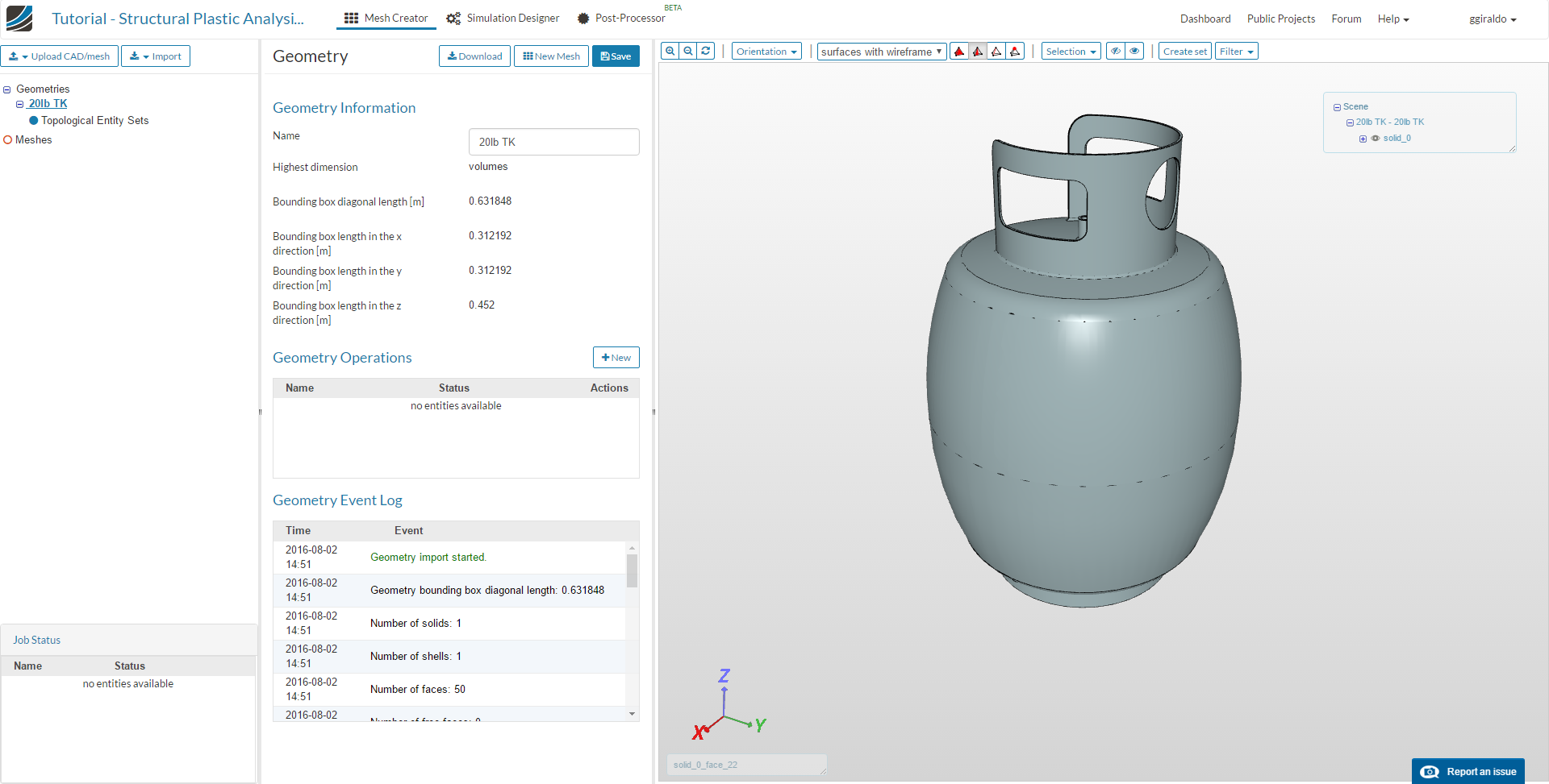
In the Mesh Creator tab, click on the geometry named 20lb - TK, then click on the New Mesh button
Select Tetrahedral Automatic for mesh type, FIrst Order for desired mesh order, 2 - Coarse for fineness and 8 computing cores. Name it Lin_Coarse for future reference:
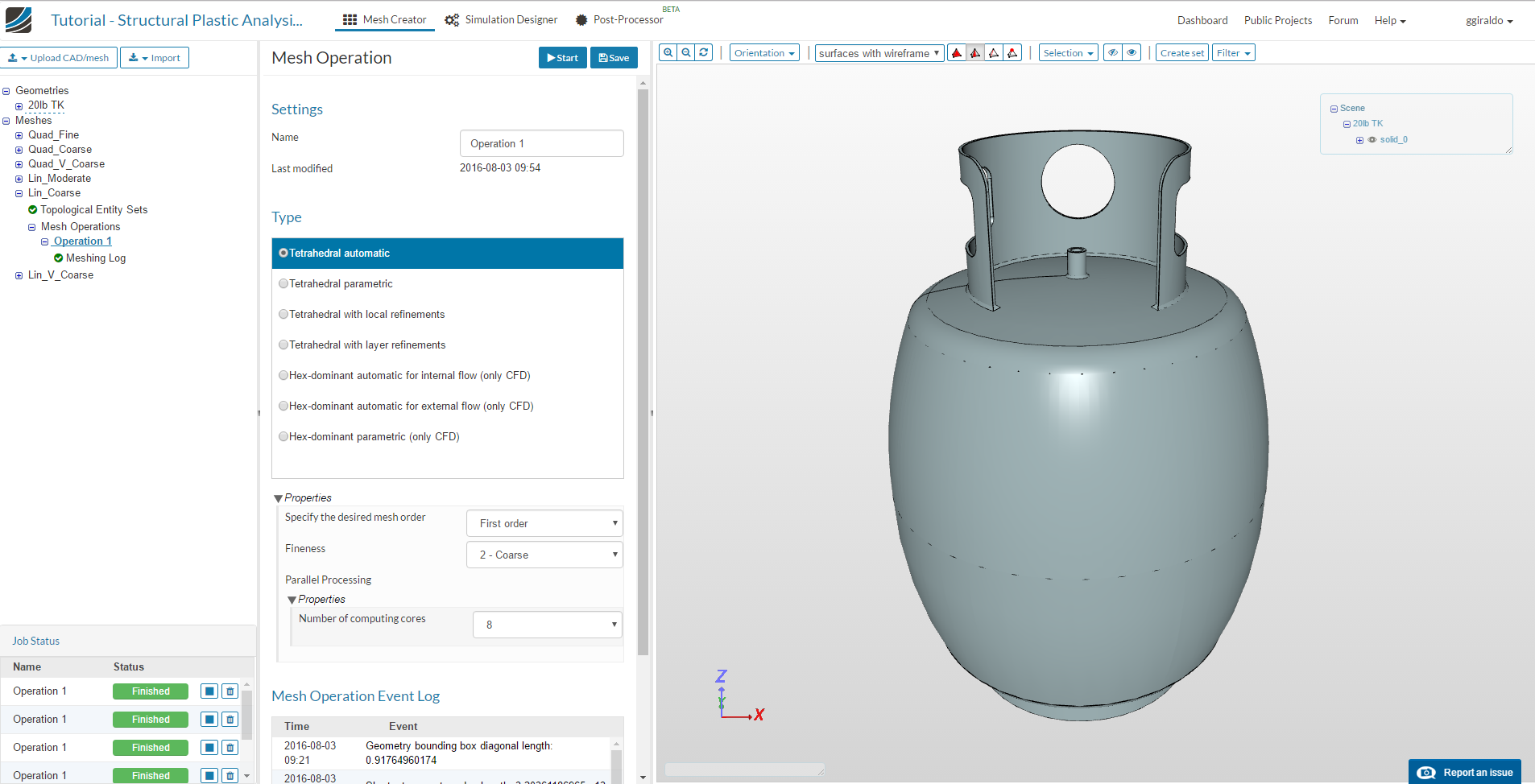
Click the Save button on the top and then Start. This will start the mesh computation on the cloud, which will take about 10 minutes to complete. Then the status will change to “Finished” and the mesh is displayed in the viewer.
Simulation Setup
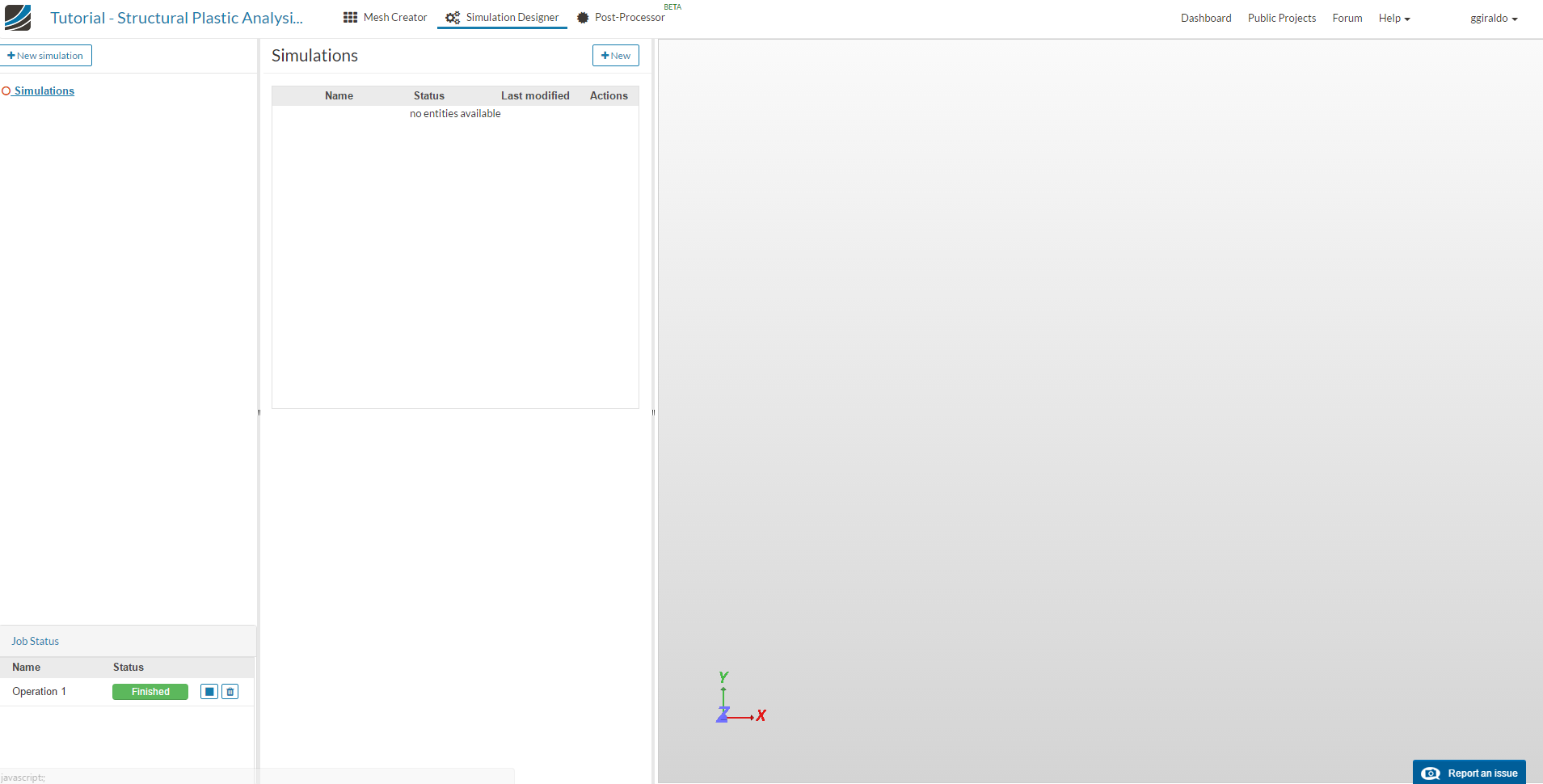
To create the simulation, go to the Simulation Designer tab and click the New Simulation button.
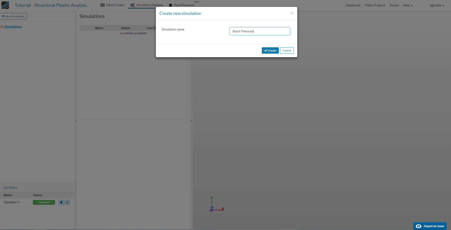
Give the simulation a name in the pop-up window, e.g.: “Burst Pressure” and click Create.
Since ours will be a non-linear structural analysis, because of the plastic material model and increasing load, select analysis type Solid Mechanics, Static analysis - advanced and Nonlinear analysis as true, then click the Save button.
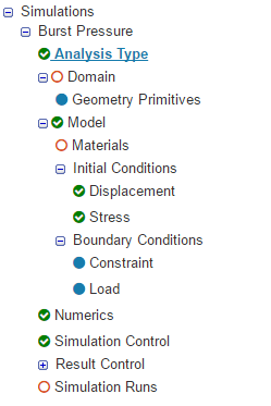
The simulation tree is created, showing the entries that we must complete:
Domain
Click on the tree item Domain at the left. Select the computed mesh Lin_Coarse and click the Save button.
- Also, when the mesh is loaded in the viewer, you can change the render mode to surfaces, for easier selection of entities.
Topological entity sets
We will create two sets of faces where we will apply boundary conditions and loads.These are:
-
Base: this will be the support face with restricted movement, corresponds to the bottom of the tank.
-
Internal: to apply the pressure load, corresponds to all internal faces.
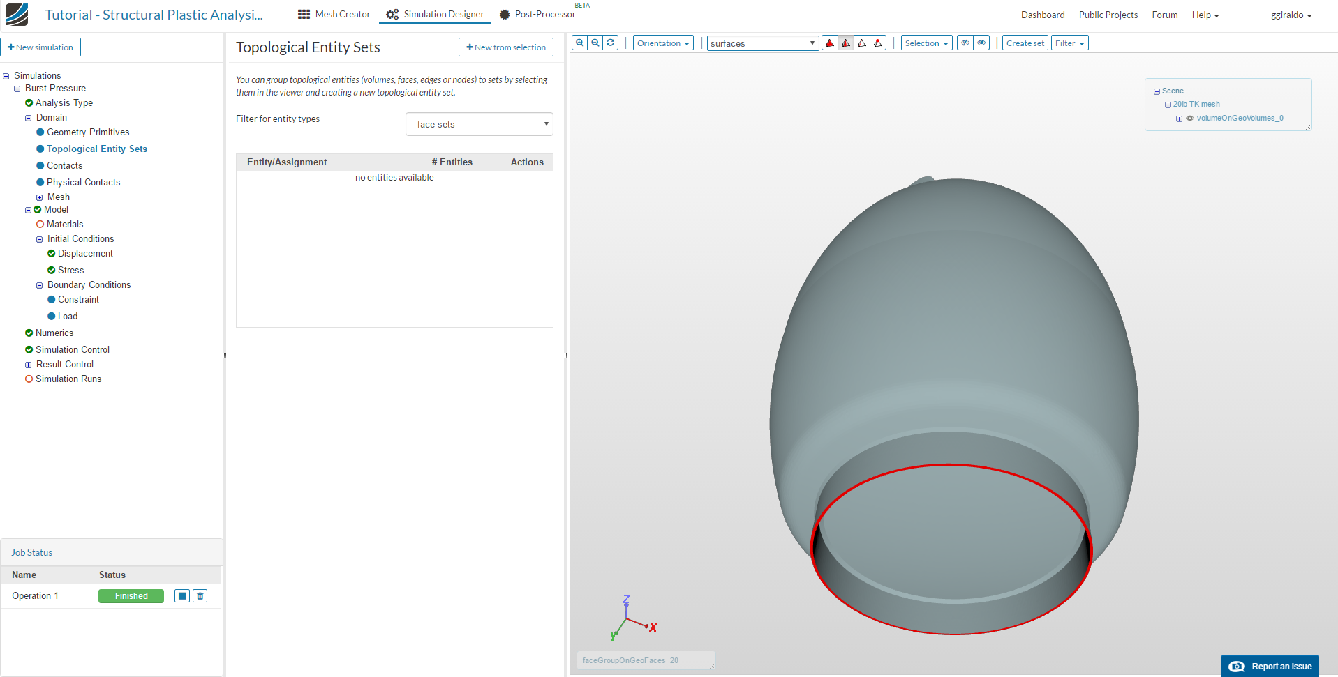
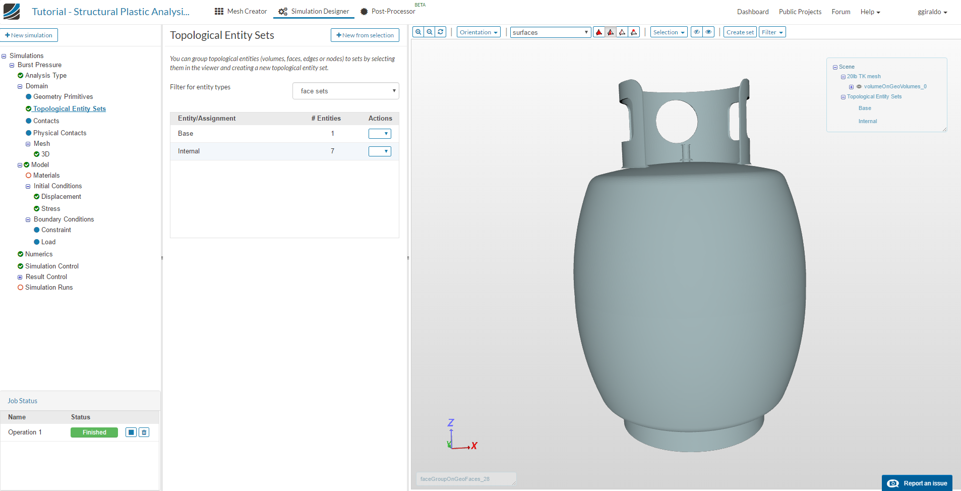
Click Topological Entity Sets in the tree, then change the filter to face sets. Make sure that selection type is Pick faces at the top of the viewer.
Rotate the model with the left mouse button and click the base face to select. It turns red as shown in the picture:
Click the New from selection button, assign the name Base, and click Create.
We repeat the process for the internal faces:
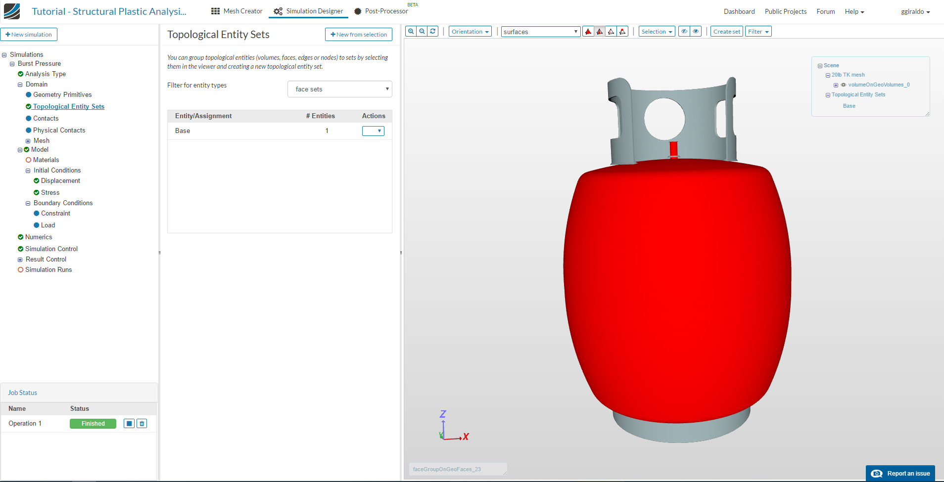
To be able to select the internal faces, we first hide the external. For this, select the external faces of the tank body, right mouse click and select Hide selection.
Select all the internal faces that would be exposed to pressure from the fluid, including the filling nozzle, seven faces in total. Name the set Internal:
Material
We will create an elastic-perfectly plastic material model, based on steel properties. Click Materials from the tree and New. Enter the following parameters:
-
Name: Steel
-
Material behavior: Plastic
-
Plastic hardening: Isotropic
-
Young’s modulus: 203e9
-
Poison´s ratio: 0.3
-
Von mises stress: define via a table. This table has to be created and uploaded, and contains the bi-linear material behavior data. Create a file in your computer using a text editor with the following content, and name it steel.csv:
strain [m/m], stress [Pa]
0.002, 410e6
0.169, 610e6
This corresponds to the plastic part of the material, a yield stress of 410 MPa with strain 0.002 and ultimate stress 610 MPa with strain 0.169. The elastic part is computed from the Young’s modulus entered above.
Click Upload file and select the created file. Name it “Steel”, and leave the separator as “comma”, because that is what we used. Select the parameters corresponding to the file and material model data:
-
Column index of strain: 1
-
Column index of stress: 2
-
Interpolation: linear
-
Left-side extrapolation: constant
-
Right-side extrapolation: none. This will make the simulation stop when rupture would occur.
Lastly, select the volume to apply the material and click Save.
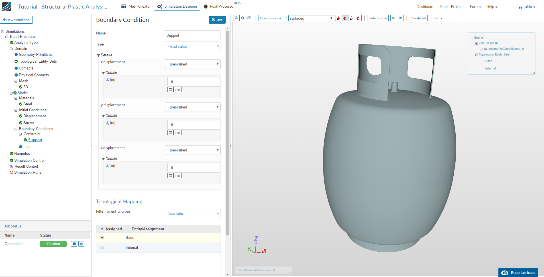
Constraint
Here we will apply the fixed degrees of freedom. Select Constraint from the tree and click New. Name it Support and leave all values fixed at zero. Change the filter to face sets and select the created Base. Cick Save.
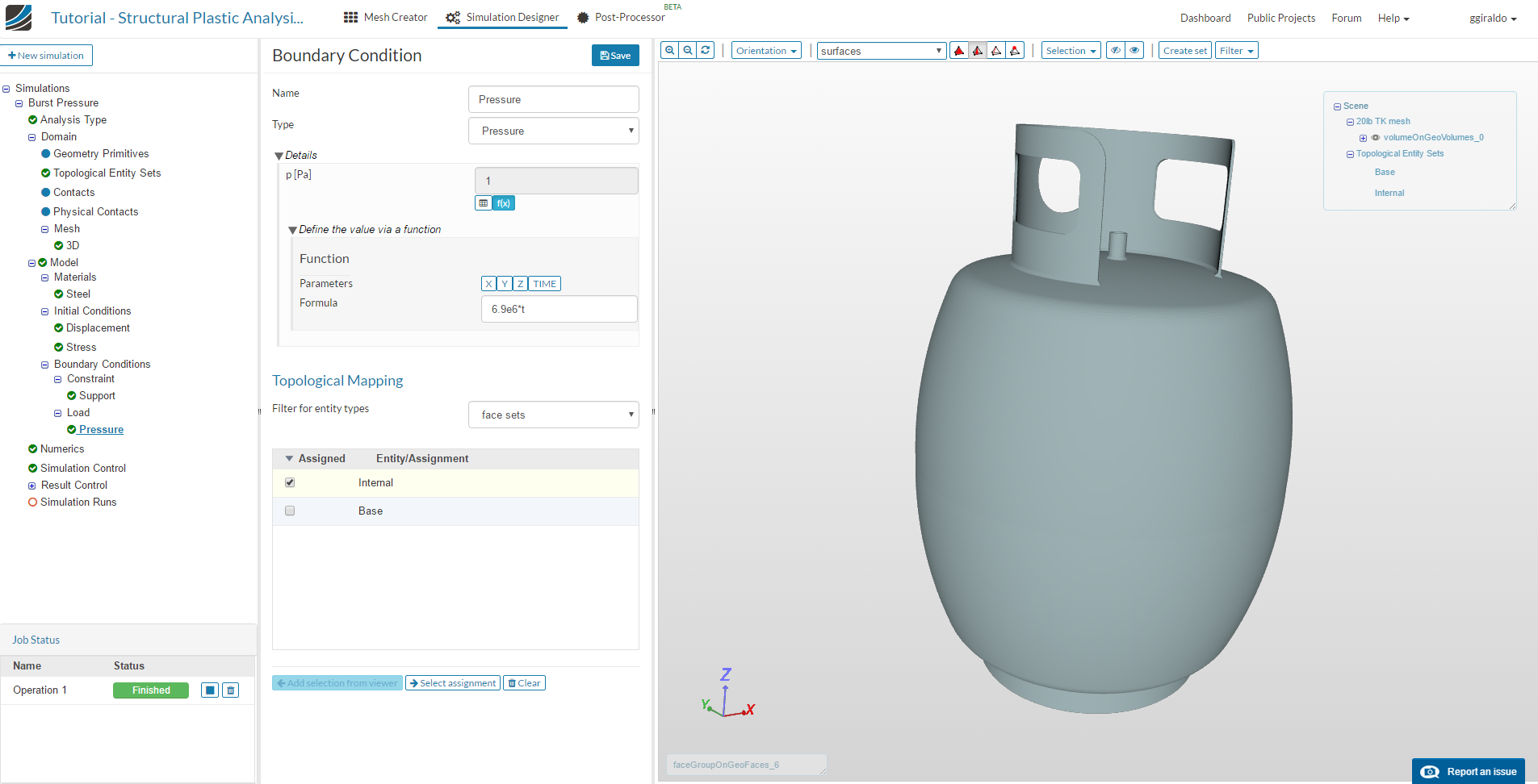
Load
Here we will apply the increasing internal pressure. Select Load from the three and click New. Name it Pressure and leave type as pressure. In the value field, select Function, the button f(x). Enter the formula 6.9e6*t. As our simulation will run from t=0 to t=1, this will make the pressure go from 0 to the maximum value 6.9 MPa. Then select the face set we created before Internal and save.
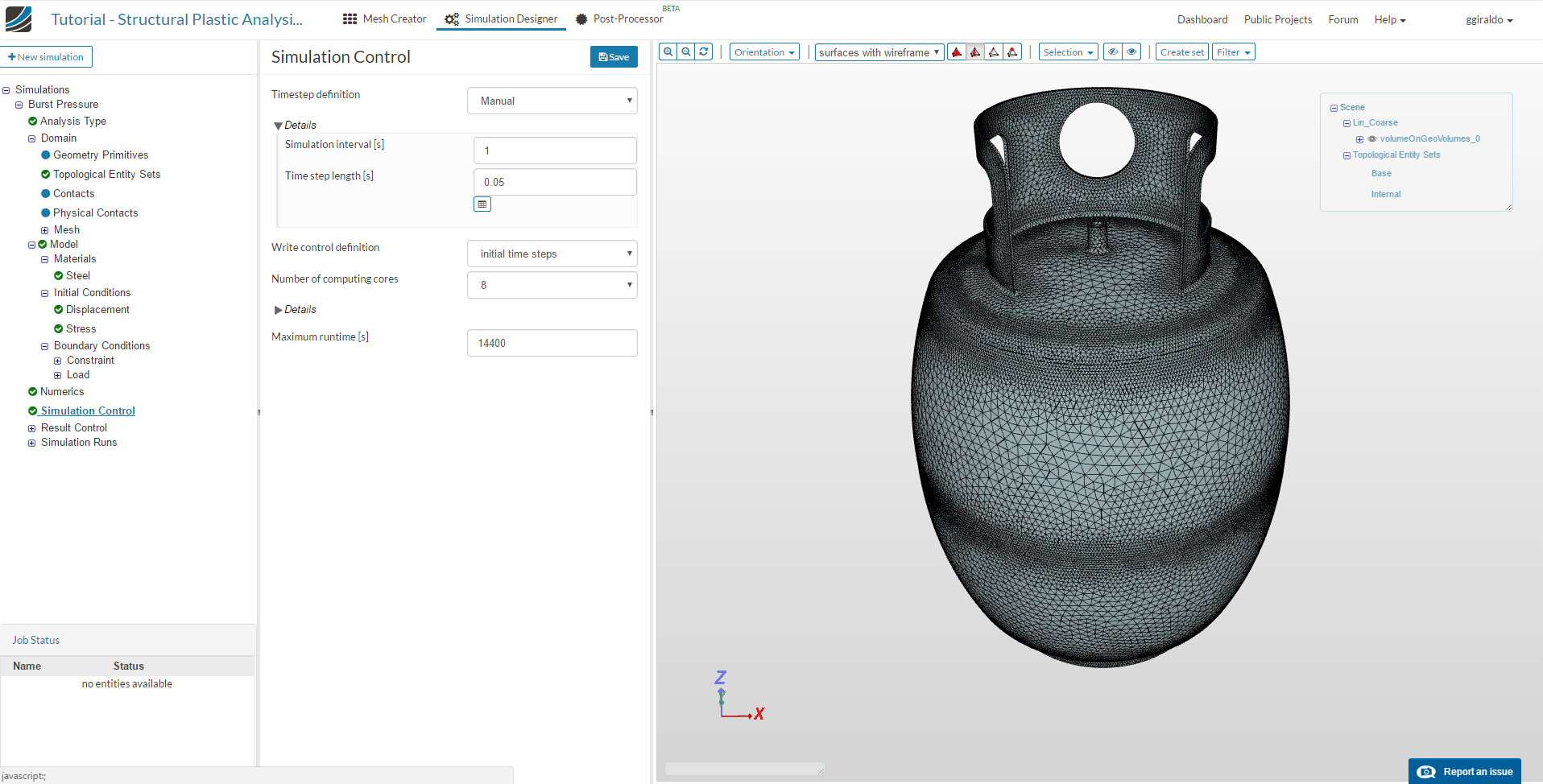
Simulation Control
We will set the default time step to 0.05 and leave the simulation time as 1, to get 20 steps in our result. Computing cores set to 8 and maximum runtime to 14400. Save.
Create run and execute
Click Simulation Runs in the tree and click New. You can also execute the check option to search for obvious errors. Name it Run-Burst, Create and then Start.
Posprocessing
We will create some useful visualizations for plastic analysis. First we will see deformation at real scale. Plastic deformations are usually big, so we should be able to see deformations at 1:1 scale.
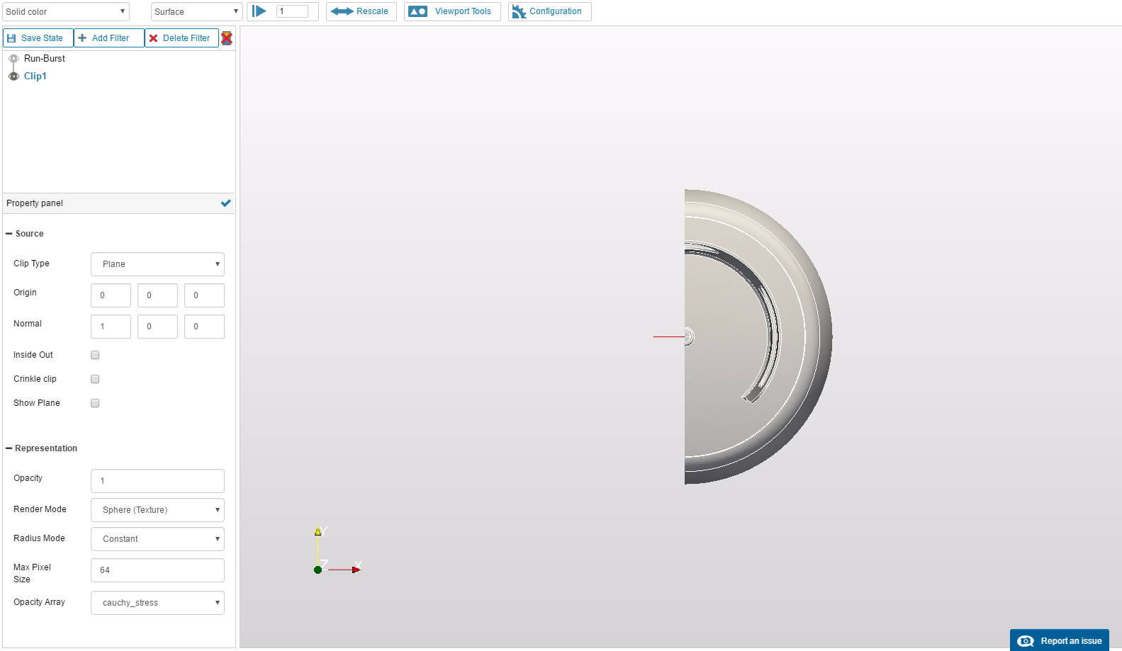
Open the Post-Processor tab and click on Solution Fields under Run-Burst in the tree at the left. This will load the paraview web viewer on the result data. Click on Add Filter and select Clip. Input the following parameters:
-Origin: (0, 0, 0)
-Orientation: (1, 0, 0)
-Show Plane: uncheck
Click apply (the blue checkmark button at the middle) and hide the Run-burst data with the “eye” button:
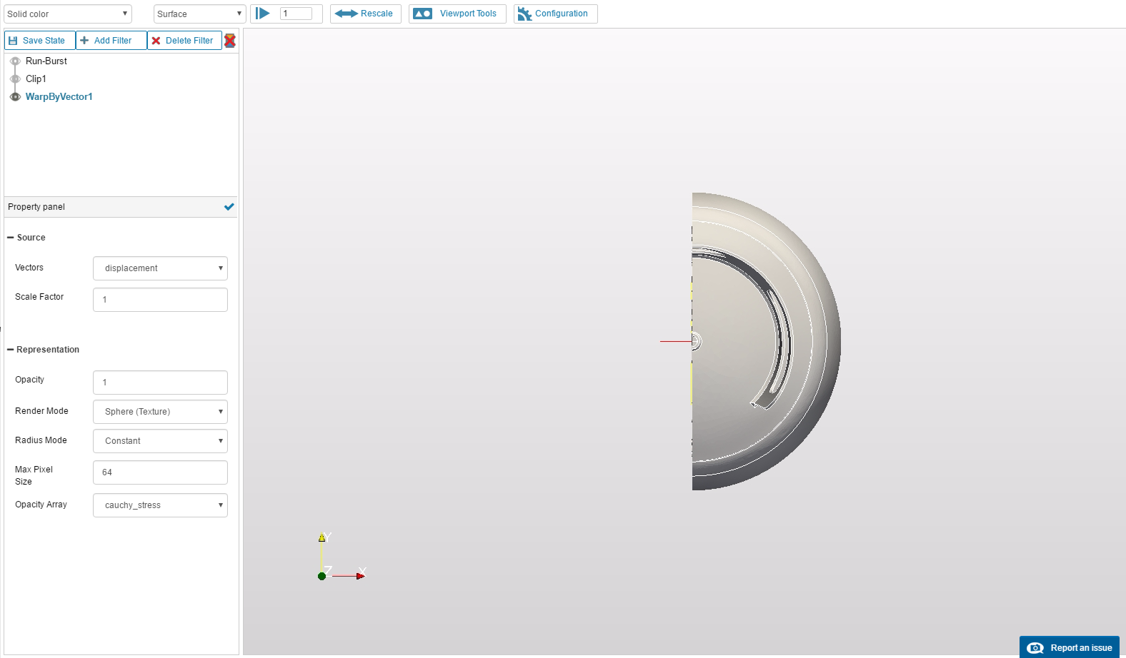
Now select Add Filter again with Clip 1 selected. Select the Warp by vector filter. Leave parameters as default, the important one here is Scale equal to 1. Click apply, hide the Clip1 data and select the Array name as Solid Color:
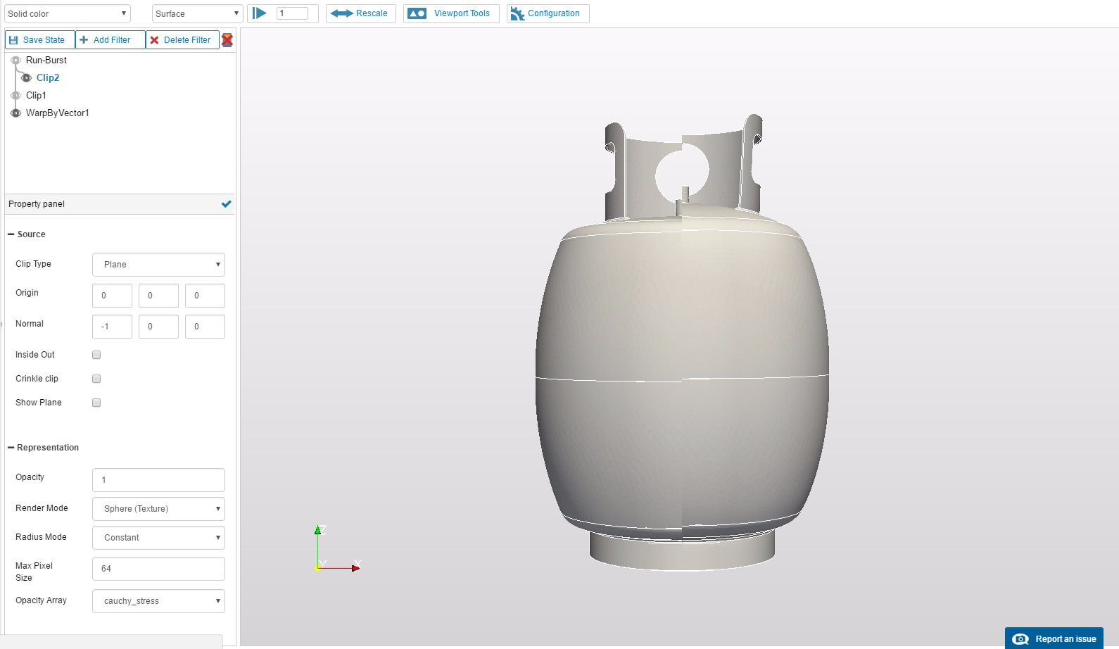
Now we will add the other half of the tank, undeformed, to compare. Select the Run-Burst data element and Add Filter. Select Clip, with following parameters:
-Origin: (0, 0, 0)
-Orientation: (-1, 0, 0)
-Show Plane: uncheck
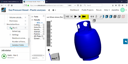
Apply changes and select Solid Color for visualization. Select the +y orientation in the Viewport Tools to better appreciate the results:
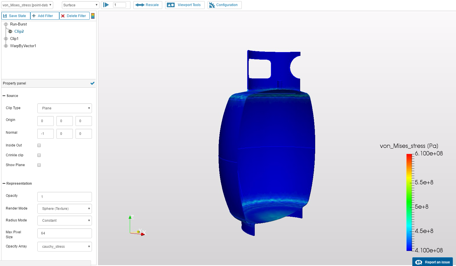
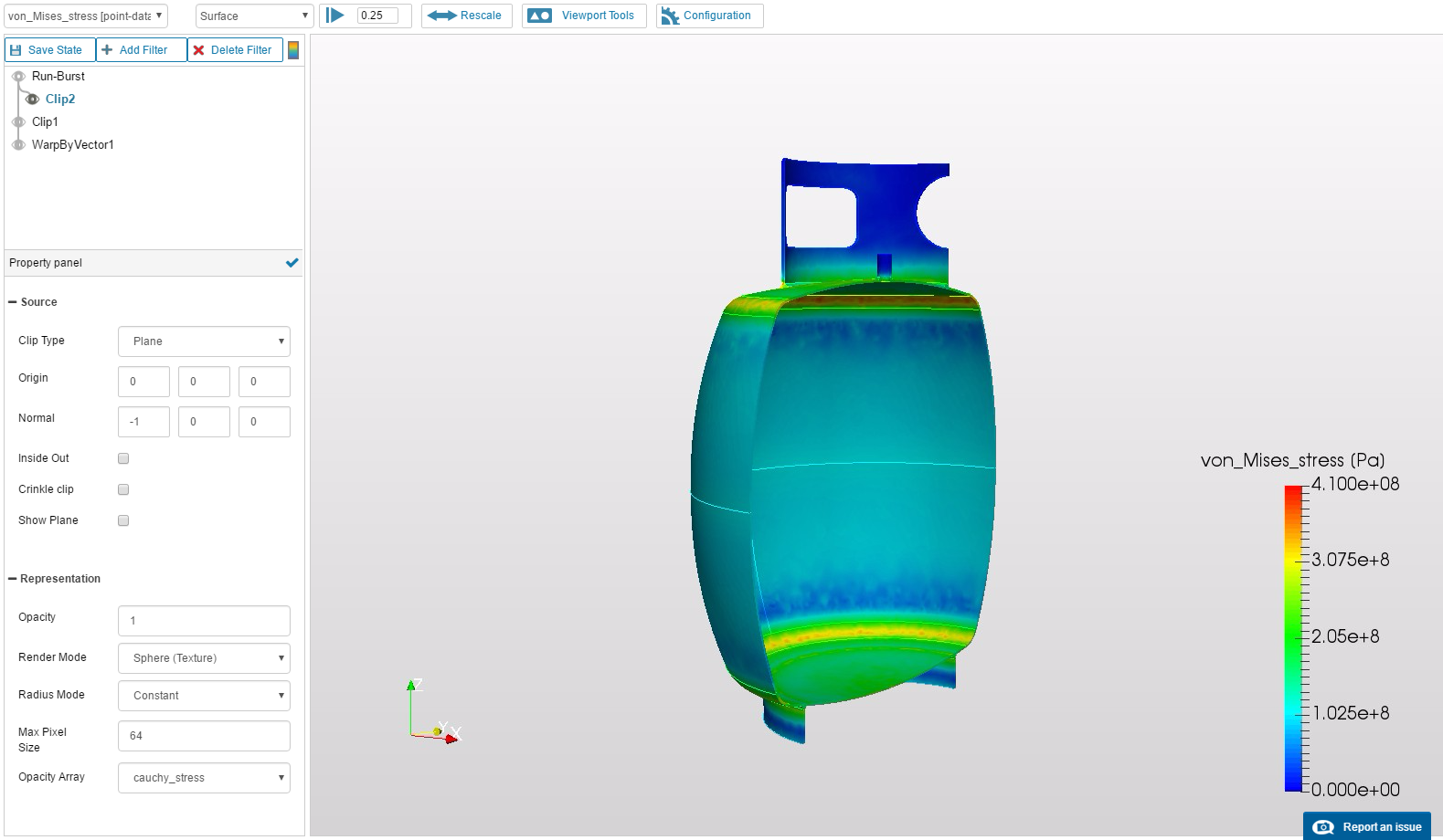
Now let’s have a look at the stress levels. Hide the WarpByVector1 results and change visualization mode of Clip2 to von_Mises_stress. Make sure that we are at the last time step, with time equal to 1. Activate the Color bar and change the data range to custom:
- Minimum: 410e6 (yield stress)
- Maximum: 610e6 (ultimate stress)
In this way, blue areas haven’t reached yield and red areas reached rupture point:
To find out when yield first occurs, change the data range to (0, 410e6). This way the visualization shows areas that have reached yield with red color. Now we navigate through time steps to find when yielding first appears. At t = 0.25 we find it:
Conclusion
So there it is, my tutorial on plasticity analysis of solids. You can keep experimenting on different postprocessing of the results or change parameters of the simulation to compare. For example, some topics we didn’t cover in the tutorial:
- How a finer mesh affects the results?
- What about second order meshes? Are they more precise?
- We didn’t reach ultimate stress levels, but what where the maximum stresses? Where are they located?
- At what internal pressure can we expect rupture to occur?
If you have any question or want to share your answers to these or any other question, feel free to post!
Hope you liked it and happy simulation!


 Great work!
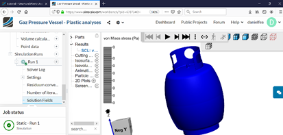
 Let us know if that worked!