Objective
In this tutorial the flow of water through a gate valve will be simulated.

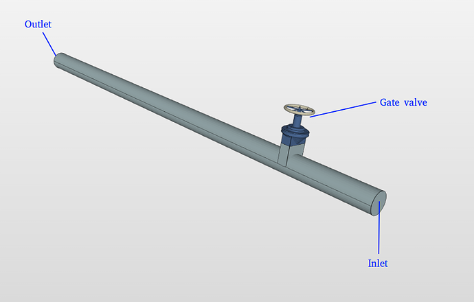
Geometry
For this tutorial a simplified geometry will be used. The geometry contains the internal cavity made by the above geometry. The geometry for can be [imported from here]
Mesh
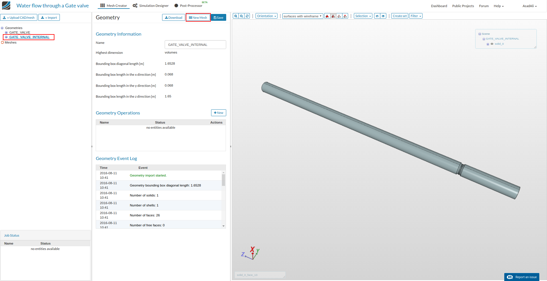
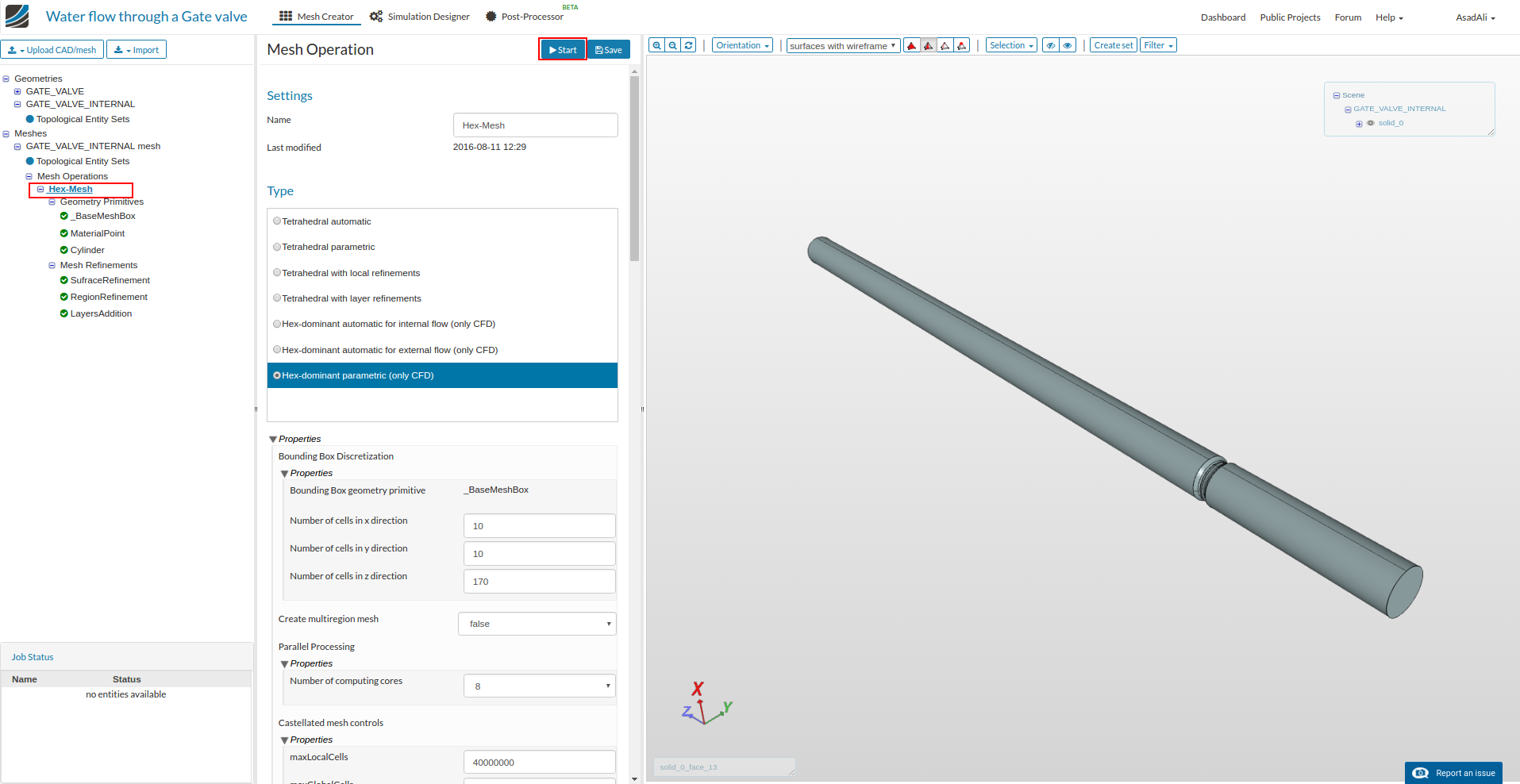
Select the GATE_VALVE_INTERNAL and then click on New Mesh. A new mesh setup will be created instantly
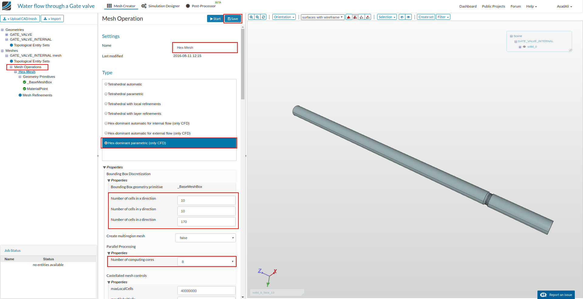
Once mesh setup is created, rename it and select Hex-dominant parametric (only CFD) for meshing. Also set the number of mesh points in each direction and set the number of computing cores for this operation. Click Save to save the selection.
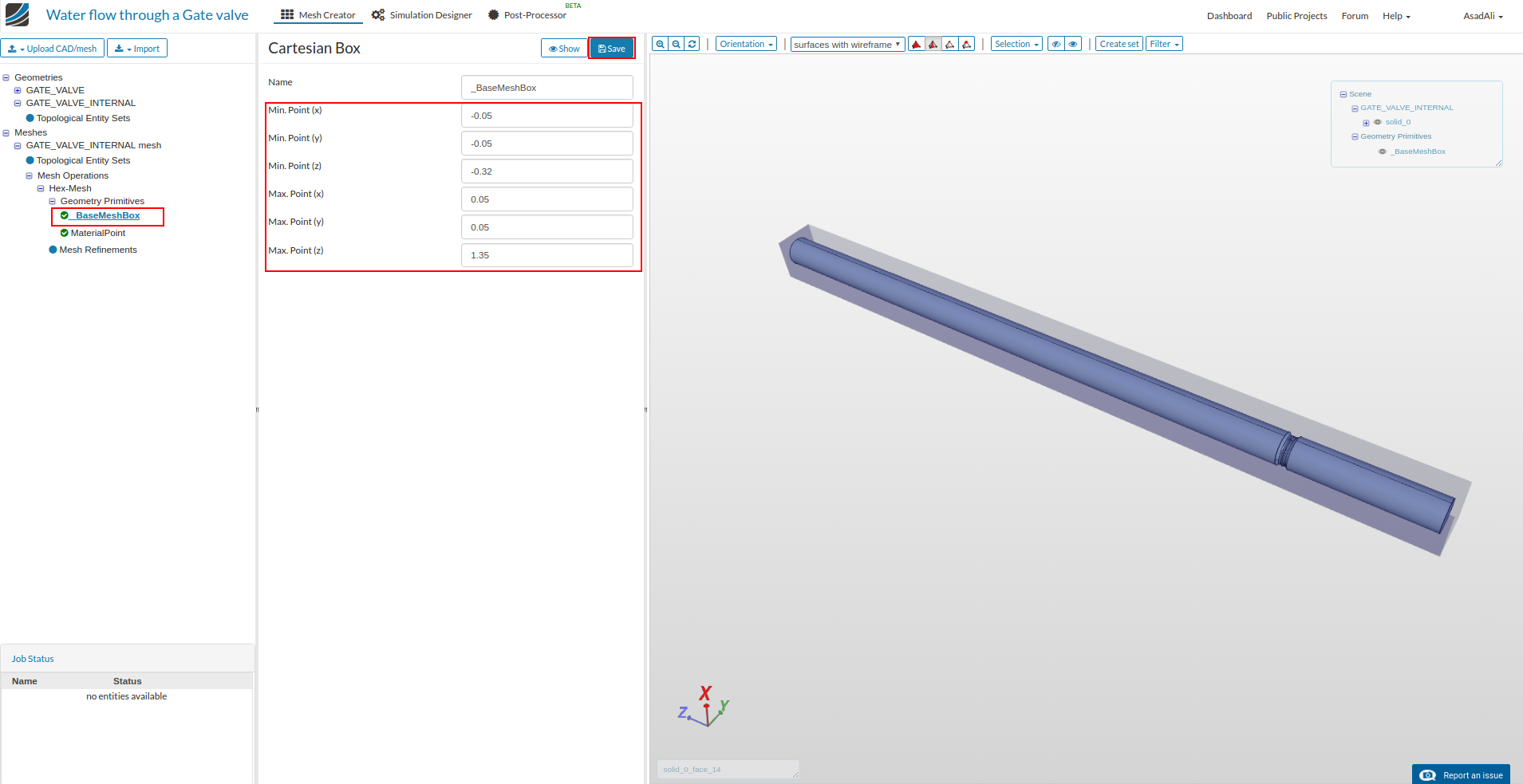
In the meshing tree move to “BaseMeshBox” and set the dimension for the box as in the image and click Save. Click Show if you want to see the box.
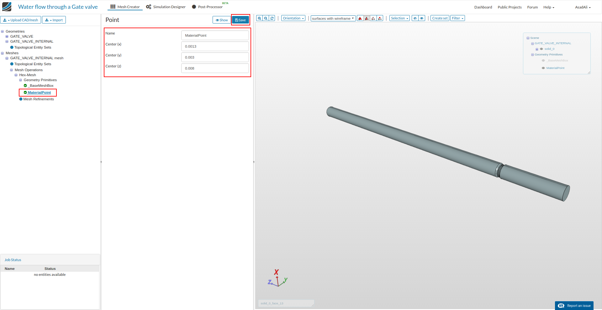
Now move to the “MaterialPoint”, set the point coordinates and save the selection.
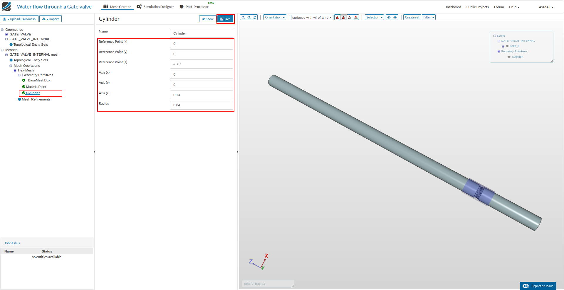
Now define a cylinder around the valve which will be used to refine the mesh in this region. Move to the Geometry Primitives, click New and the select “Cylinder”.

Set the dimensions for the cylinder and save the selection.
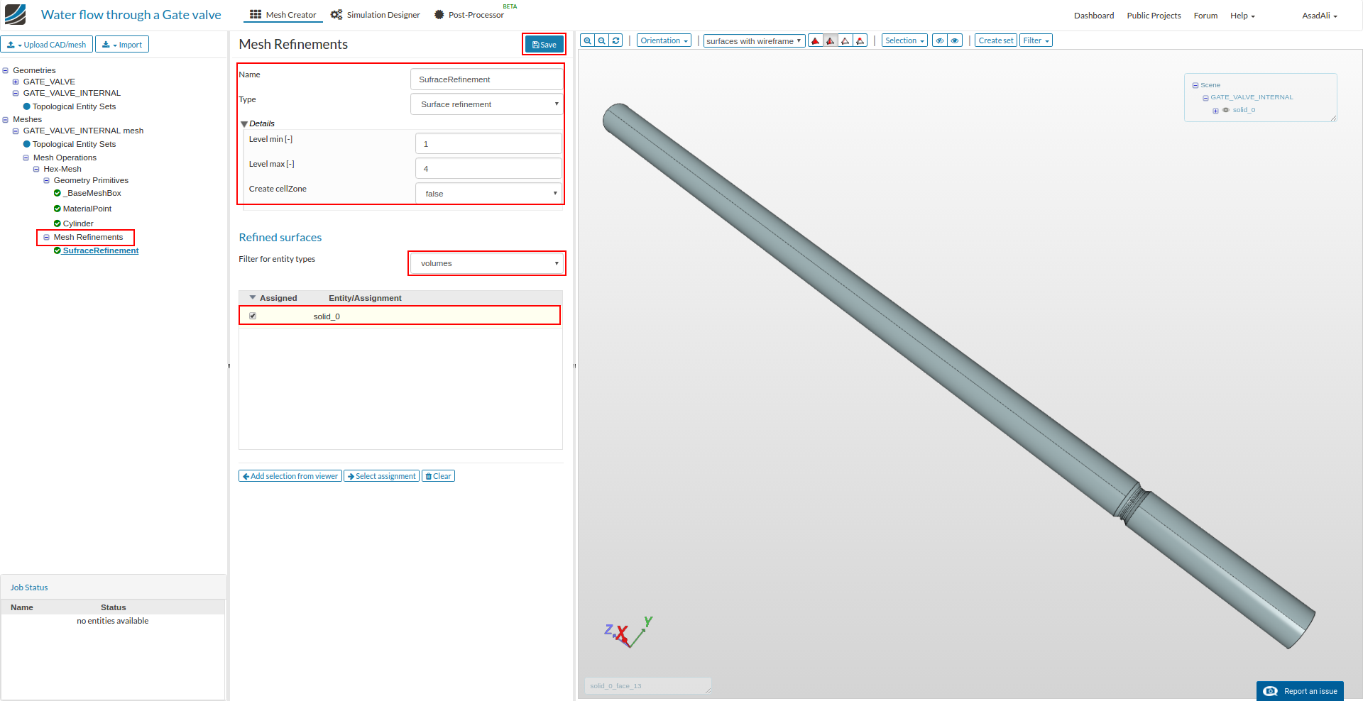
Now move to the Mesh Refinements in the meshing tree and click New to add a new mesh refinement. Rename it to “SurfaceRefinement”. Set the other parameters according to the image and save the selection.
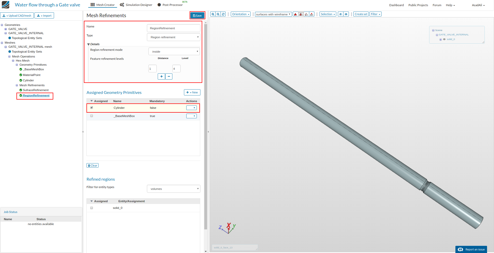
Add another mesh refinement and rename it to “RegionRefinement”. Set the parameters accordingly, select the previously made cylinder for this refinement and save selection.
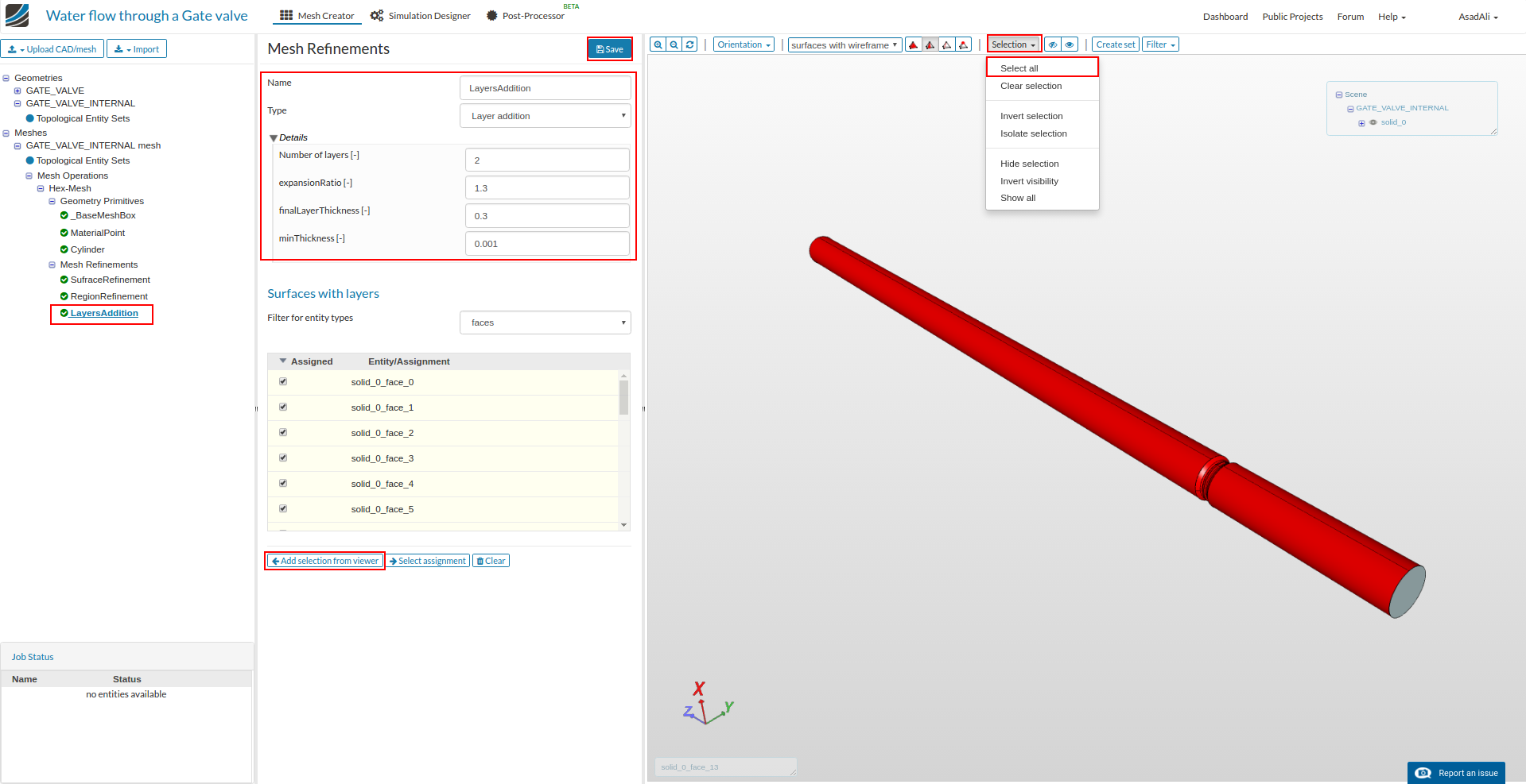
Finally add a refinement for layers addition. Rename it to “LayersAddition” and set the respective parameters. For this refinement we need to give the surface for layers addition. First select the the whole geometry by pressing Selection and the “Select all”. Now unselect inlet and outlet faces and press add from the viewer to add the selection for layers addition.
Now move to the “Hex-Mesh” (the name of mesh operation) and click Start to start the mesh operation.
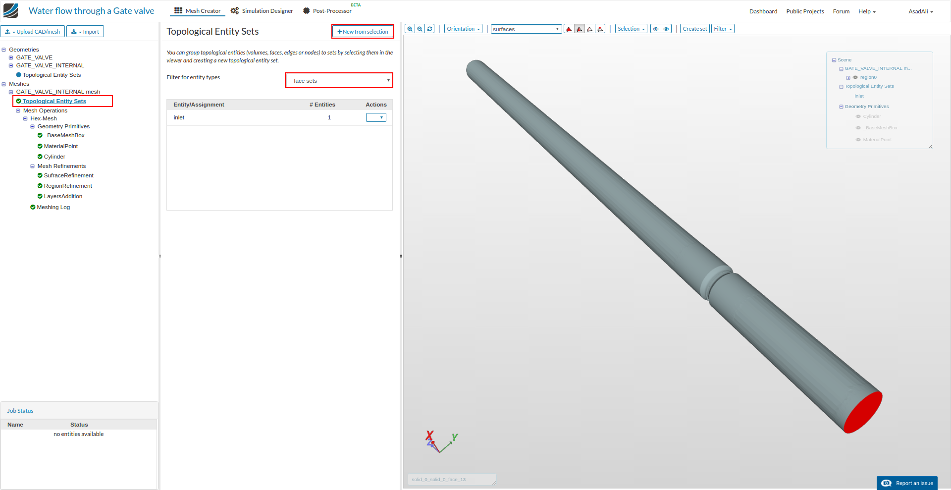
Once mesh is ready define the face set to define the boundary conditions on these face sets. Move to the Topological Entry Sets. Select the inlet face and click New from selection and name the selection to “inlet”.
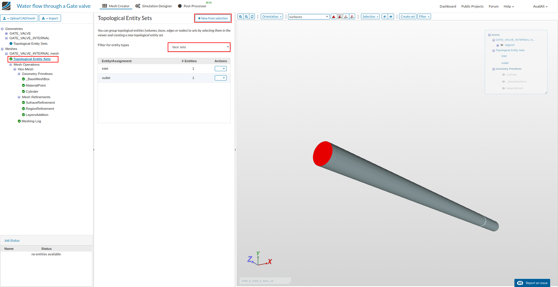
Similarly add another face set for the outlet face and name the selection ad “outlet”.
To make a face set for the walls, first select inlet and outlet one by one and hide them. Now from the “Selection” press “Select all”. This way select all the geometry other than inlet and outlet face. Now press New from selection and name it to “walls”.
Simulation
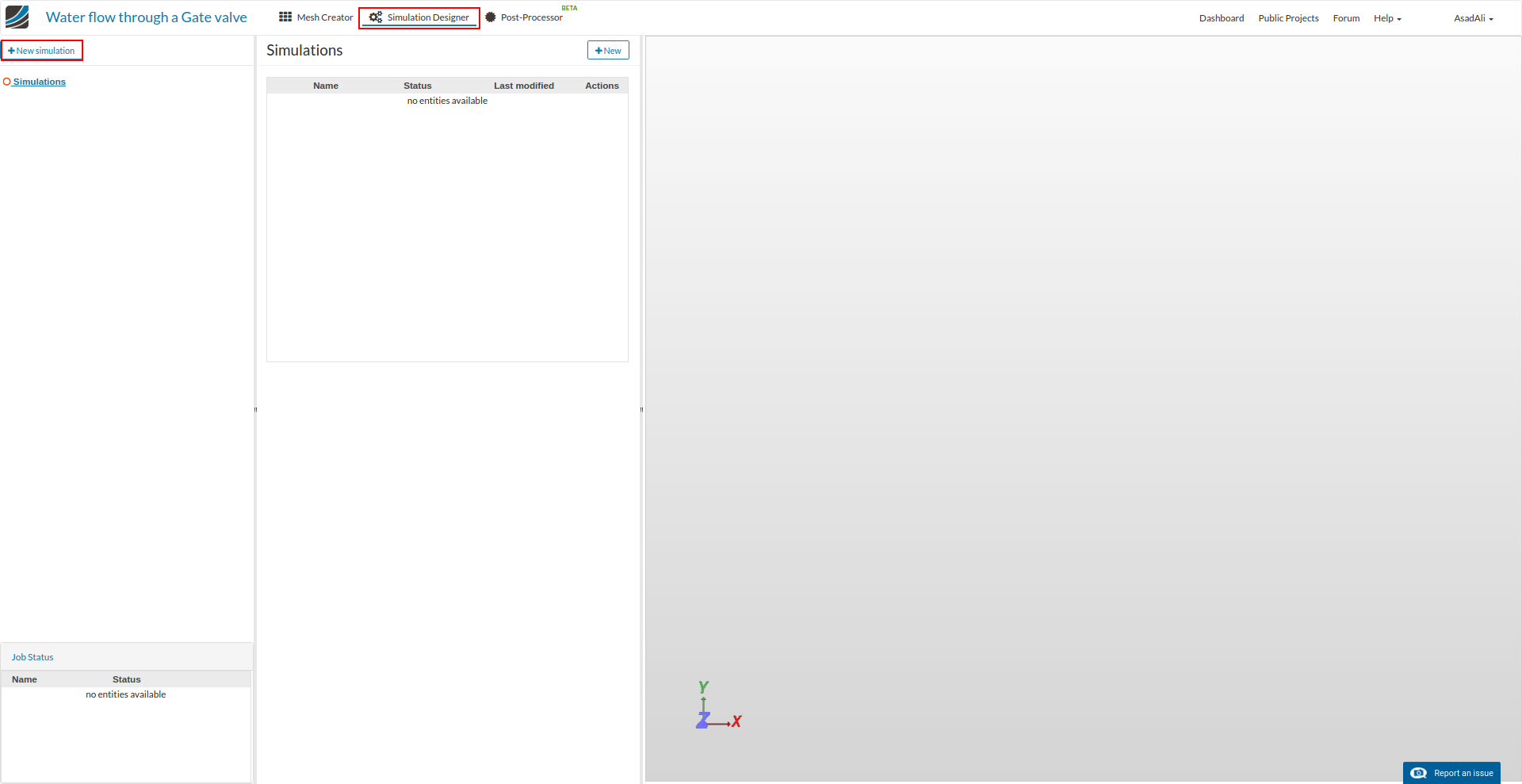
For simulation move to the Simulation Designer and click New simulation to create the new simulation setup.
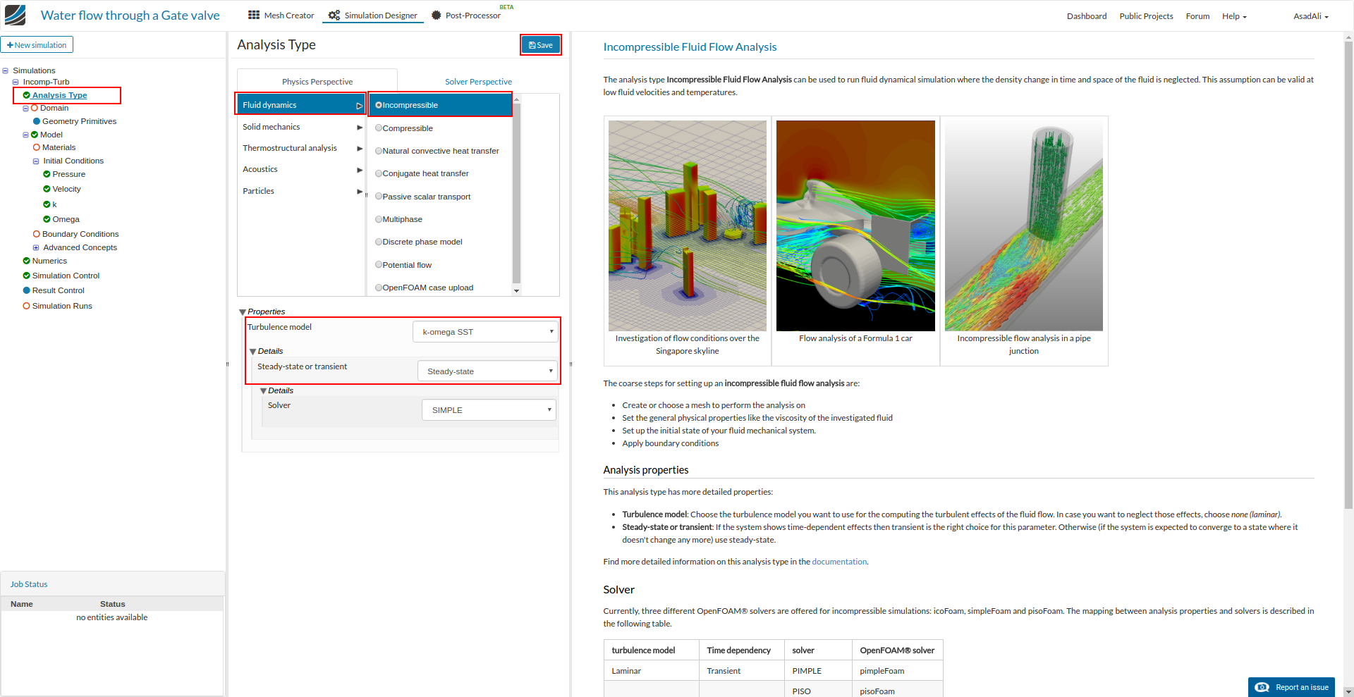
Once the mesh setup is created move to the analysis type and select Fluid mechanics and Incompressible. Set the properties of the simulation K-omegaSST for the turbulence and Steady-state. Save the selection.
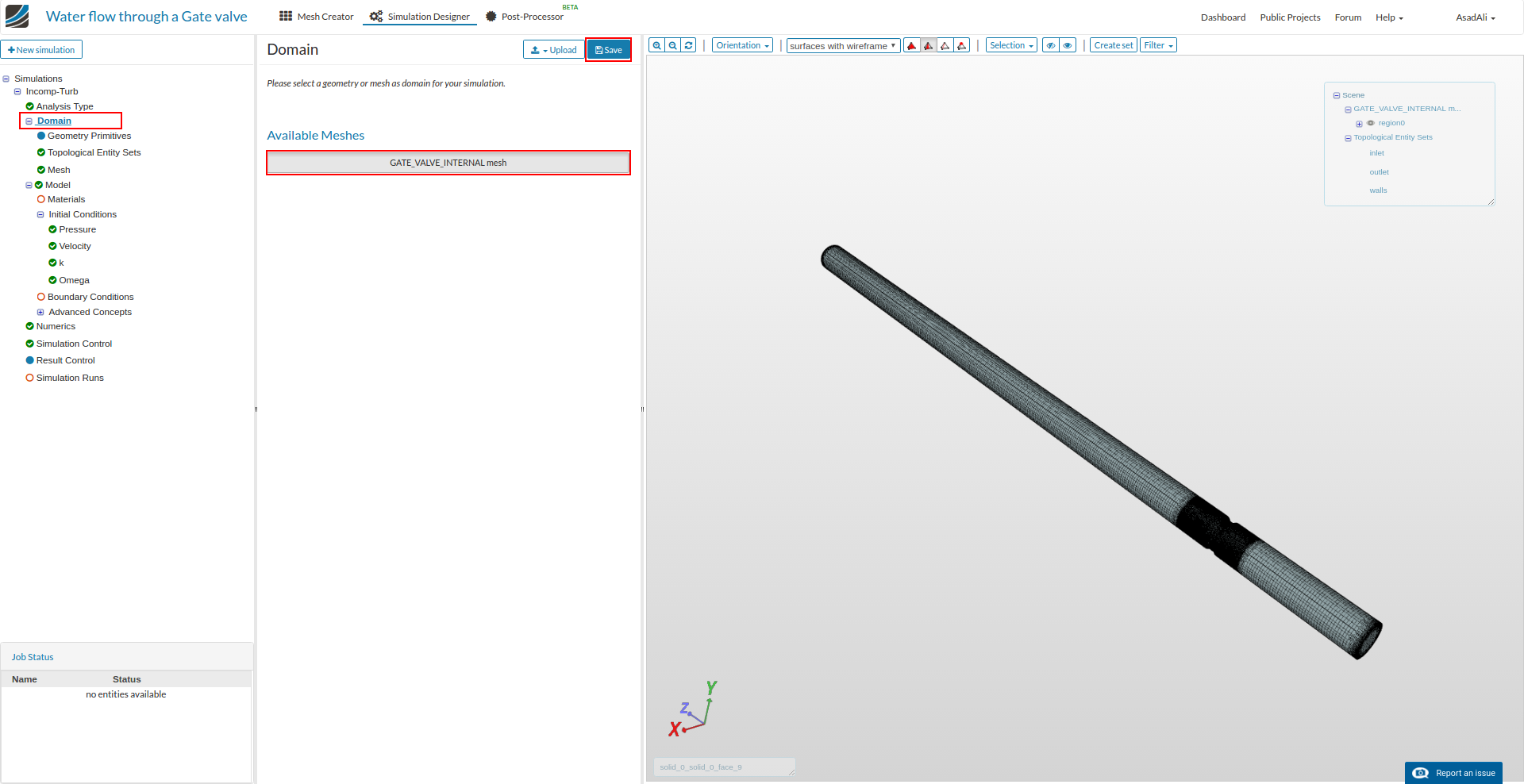
Now move to the Domain in the simulation setup tree, select the mesh and save the selection.
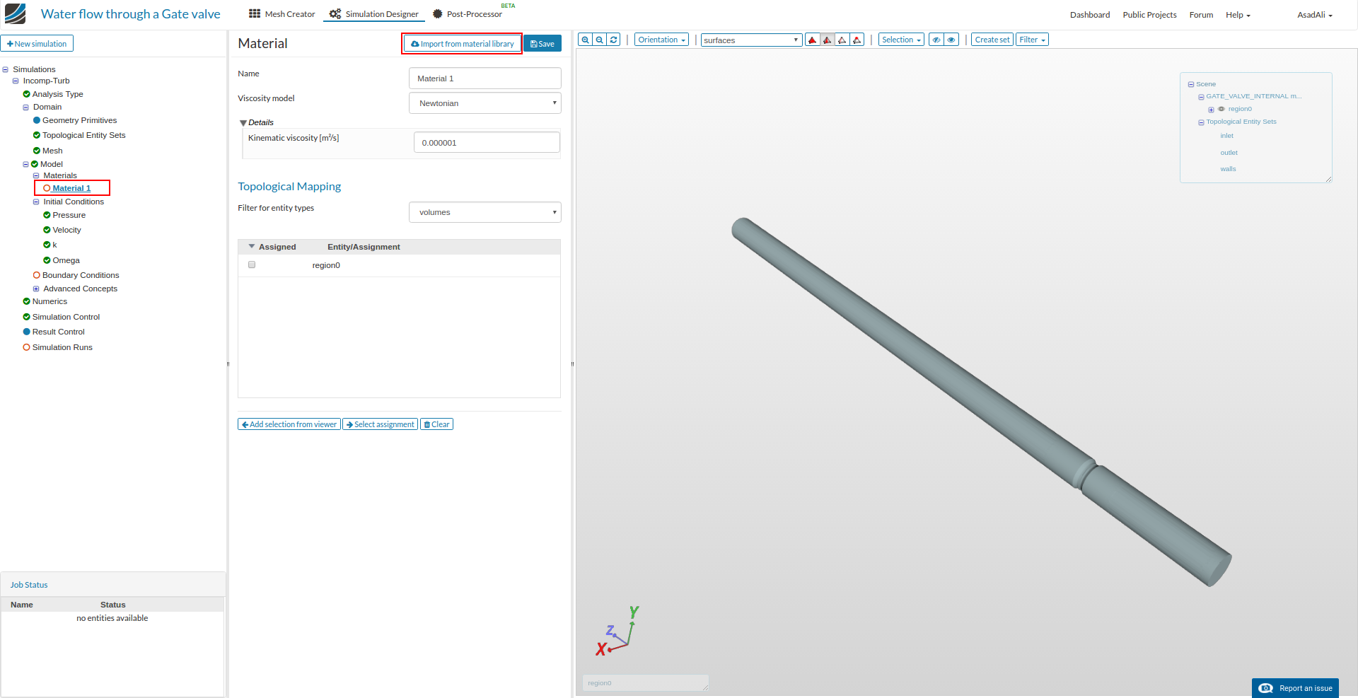
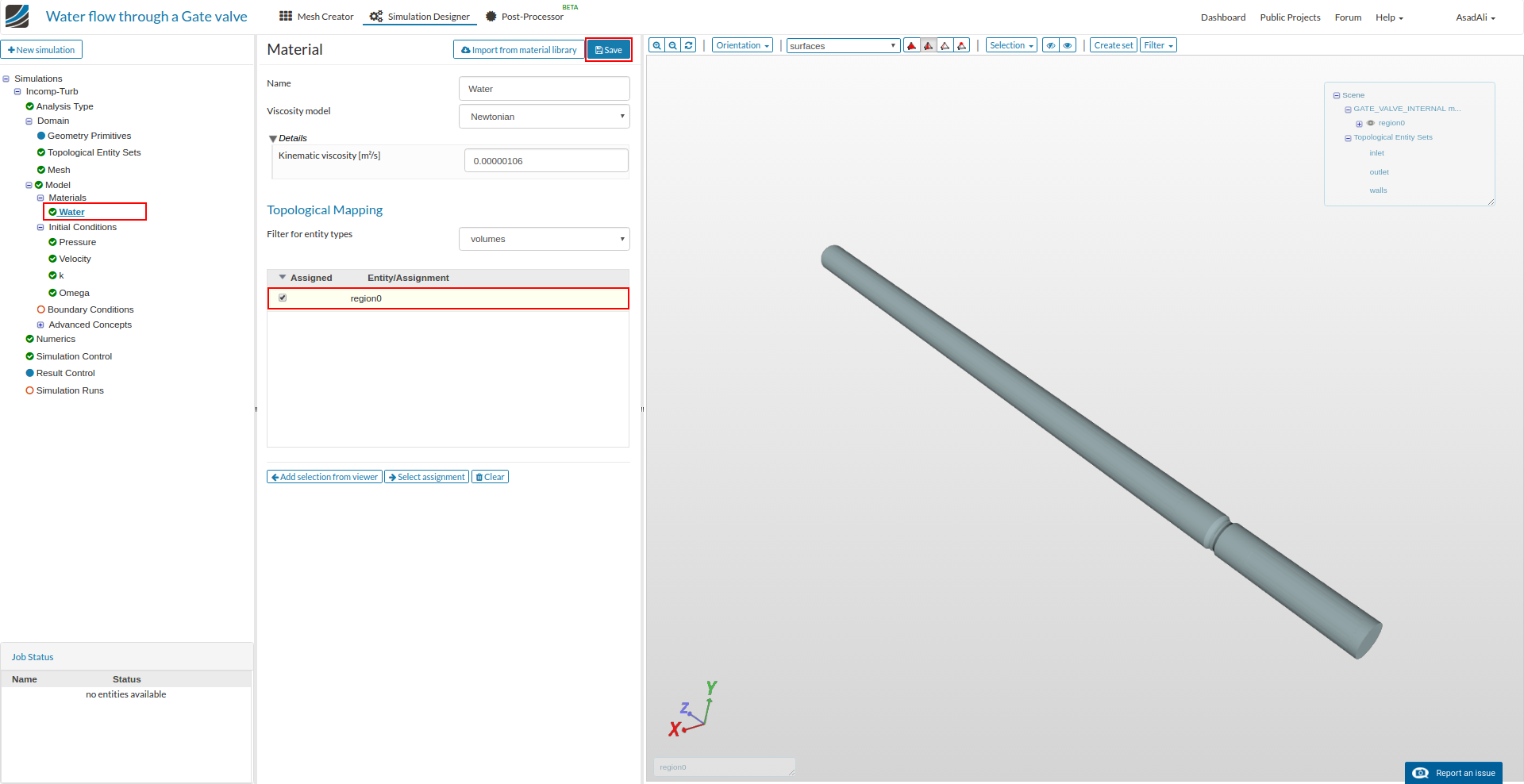
To assign the material to the domain move to the Materials and press new. Now press Import from material library to select the material from the given materials.
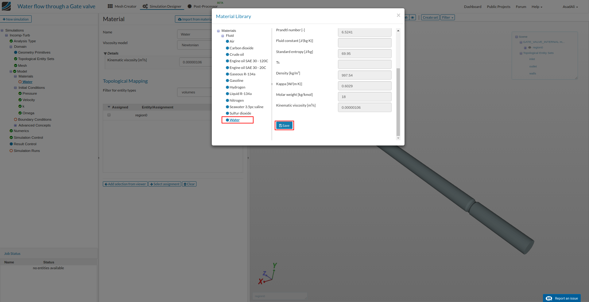
Select Water and save the selection.
Finally assign this material to the domain by moving to Water and assigning region0 volume. Save the selection.
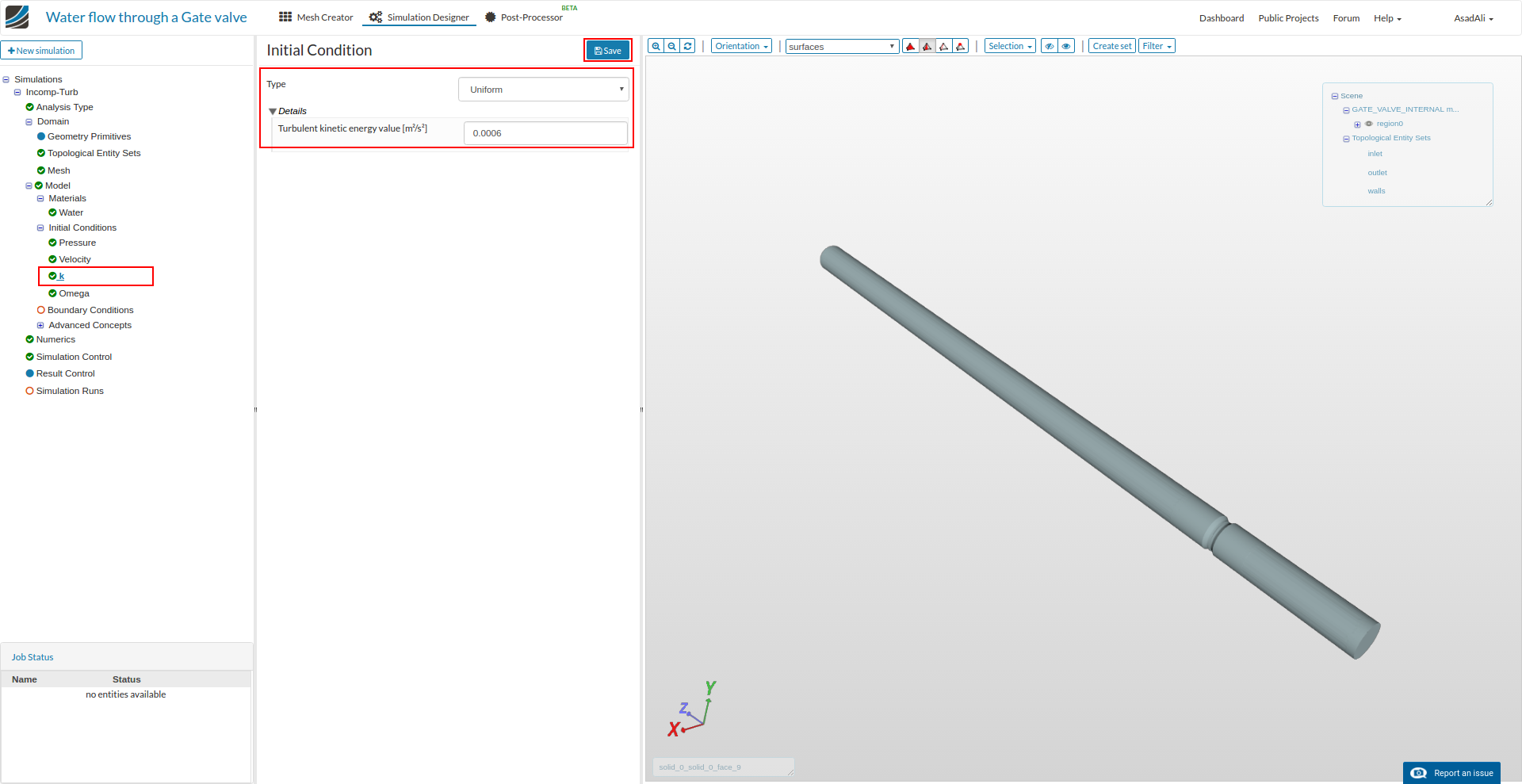
Now to change the initial conditions for turbulence parameters, move to the K and set the value accordingly.
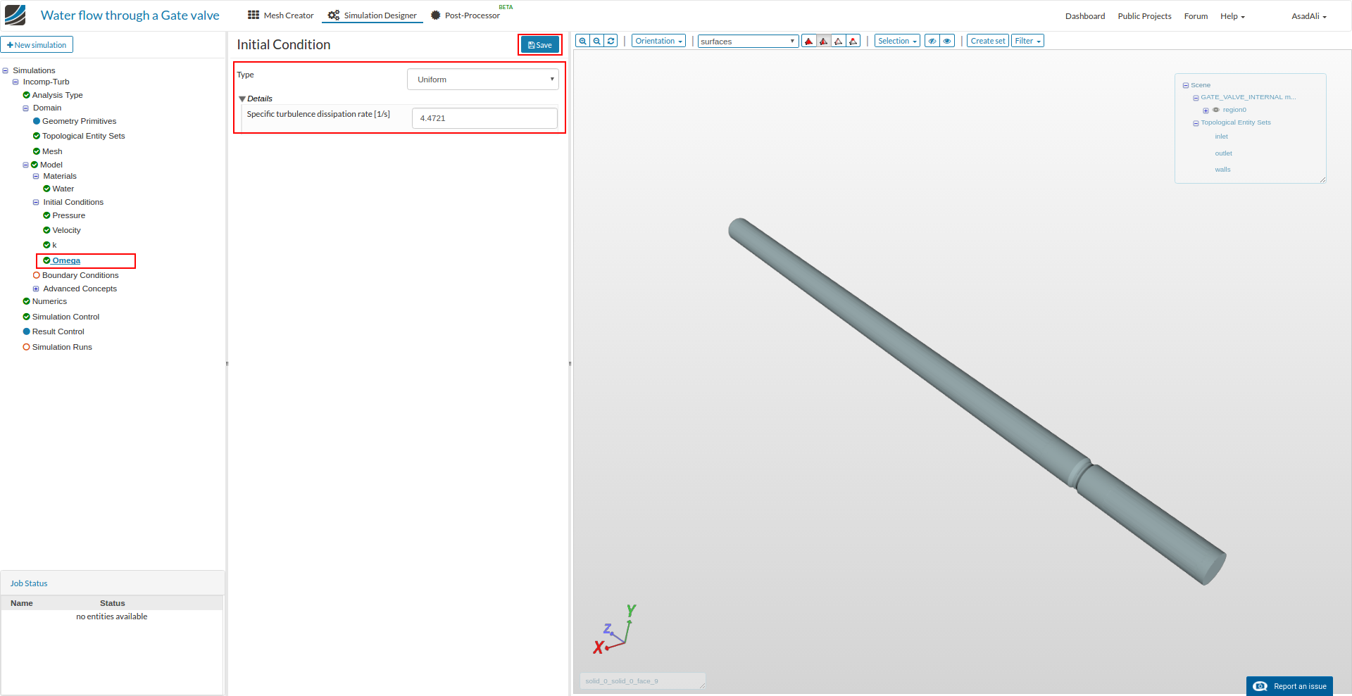
Similarly change the initial value for the omaga.
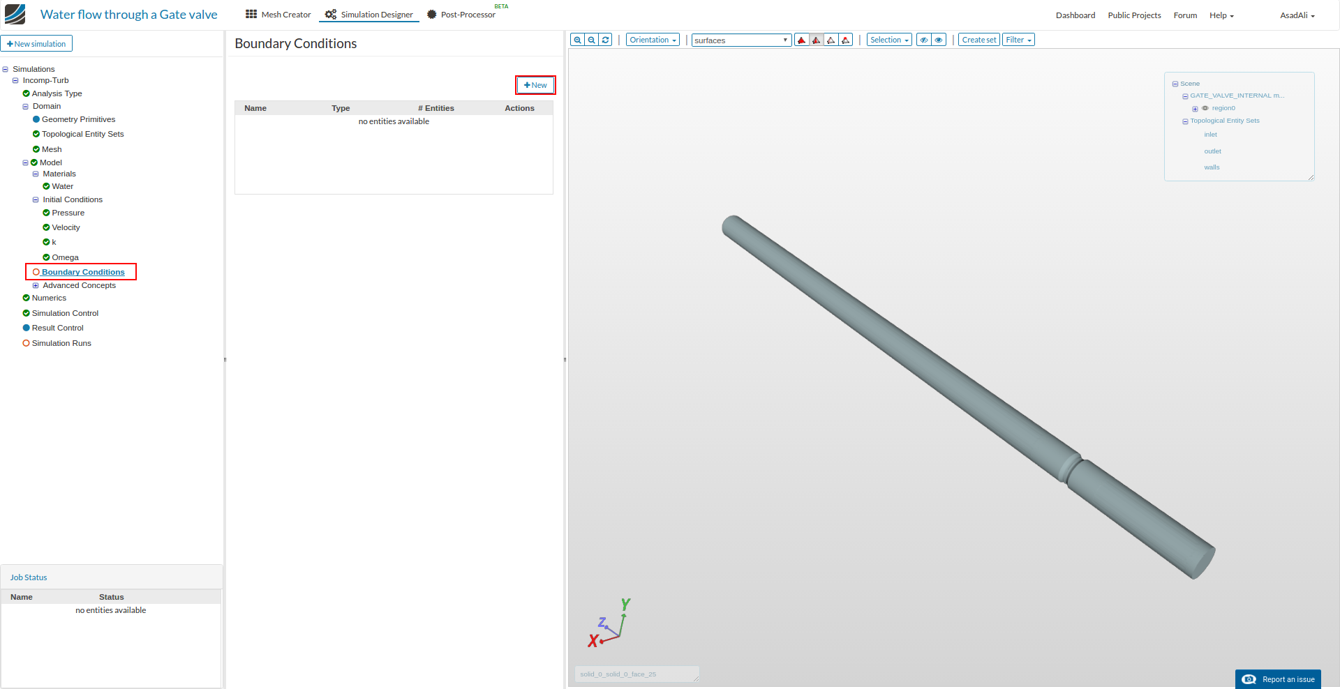
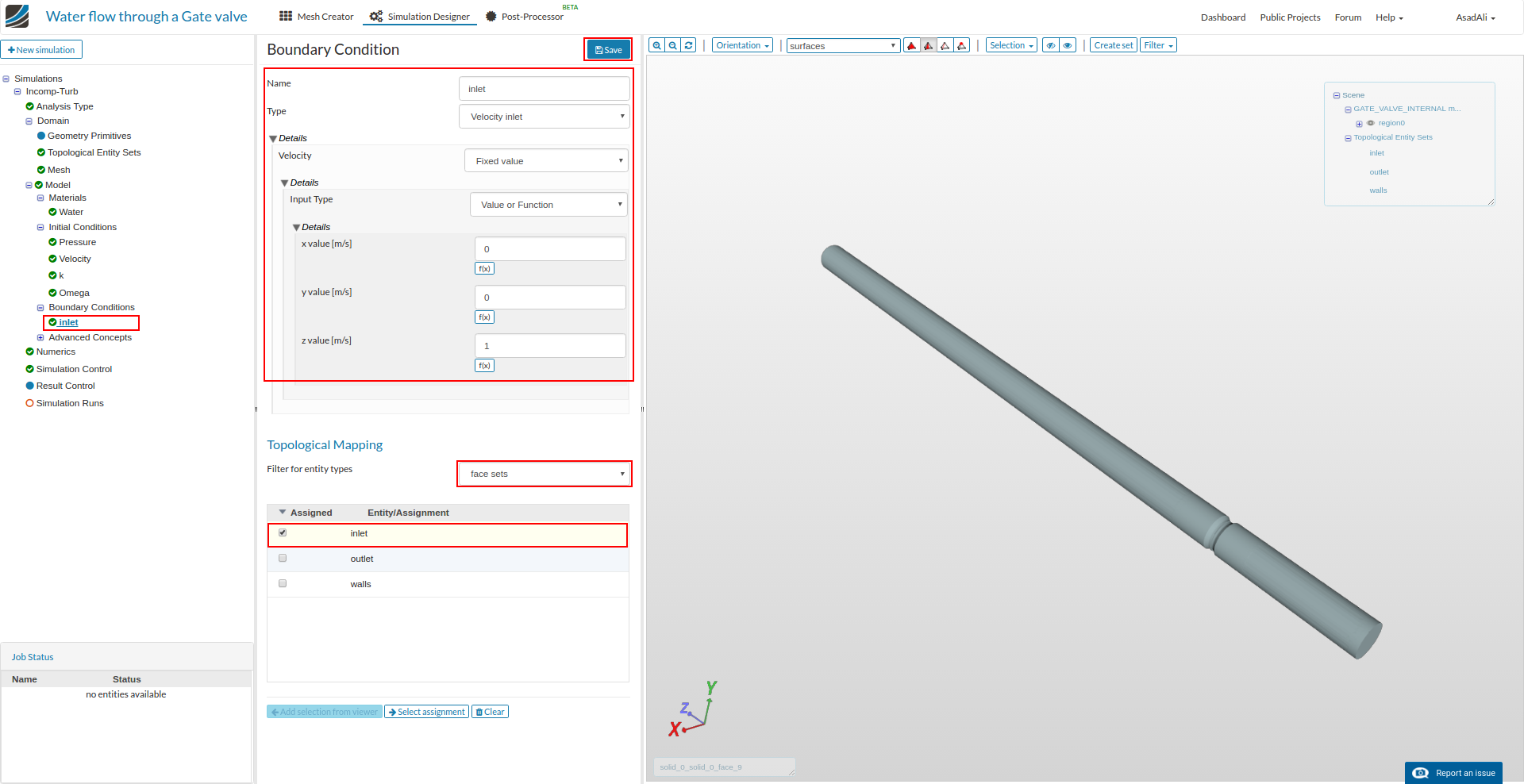
Now to add the boundary conditions move to the Boundary Conditions and press New to add a new boundary condition.
Rename the boundary condition to the “inlet”. Set the velocity inlet for this boundary condition and set other parameters accordingly. Assign the “inlet” face set to this boundary condition and save the selection.
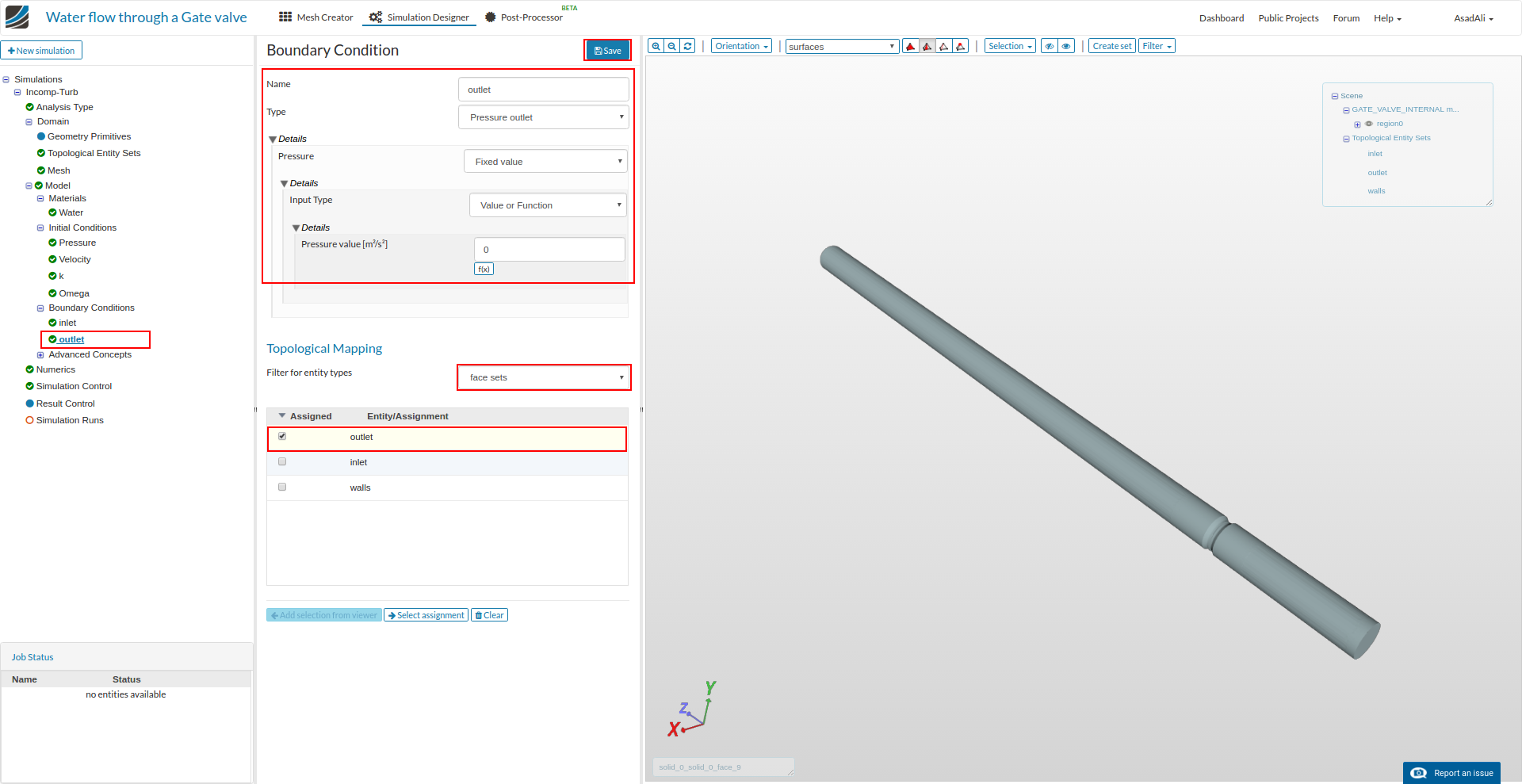
Similarly add a new boundary condition for the outlet. Rename it to “outlet”, set the pressure outlet for this boundary. Set all the parameters according to the image and save the selection.
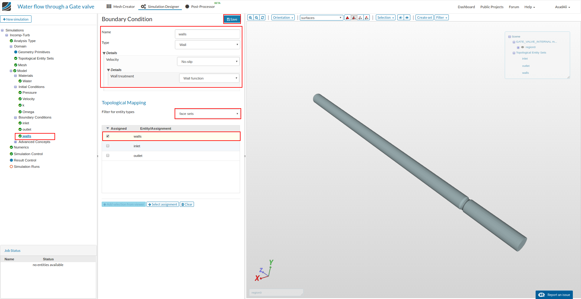
Finally add a boundary condition for the walls, assign the “walls” face set, set the respective parameters and save the selection.
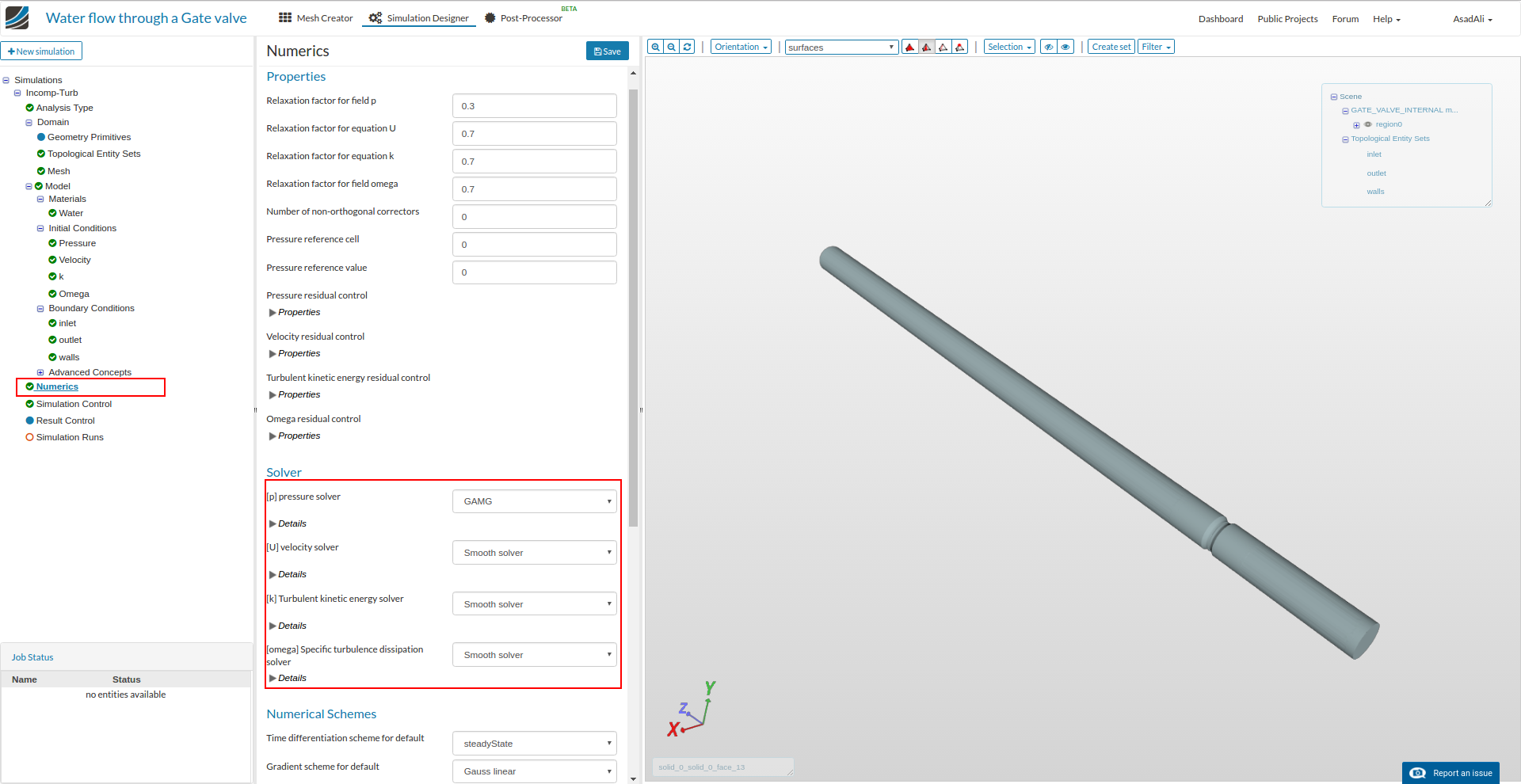
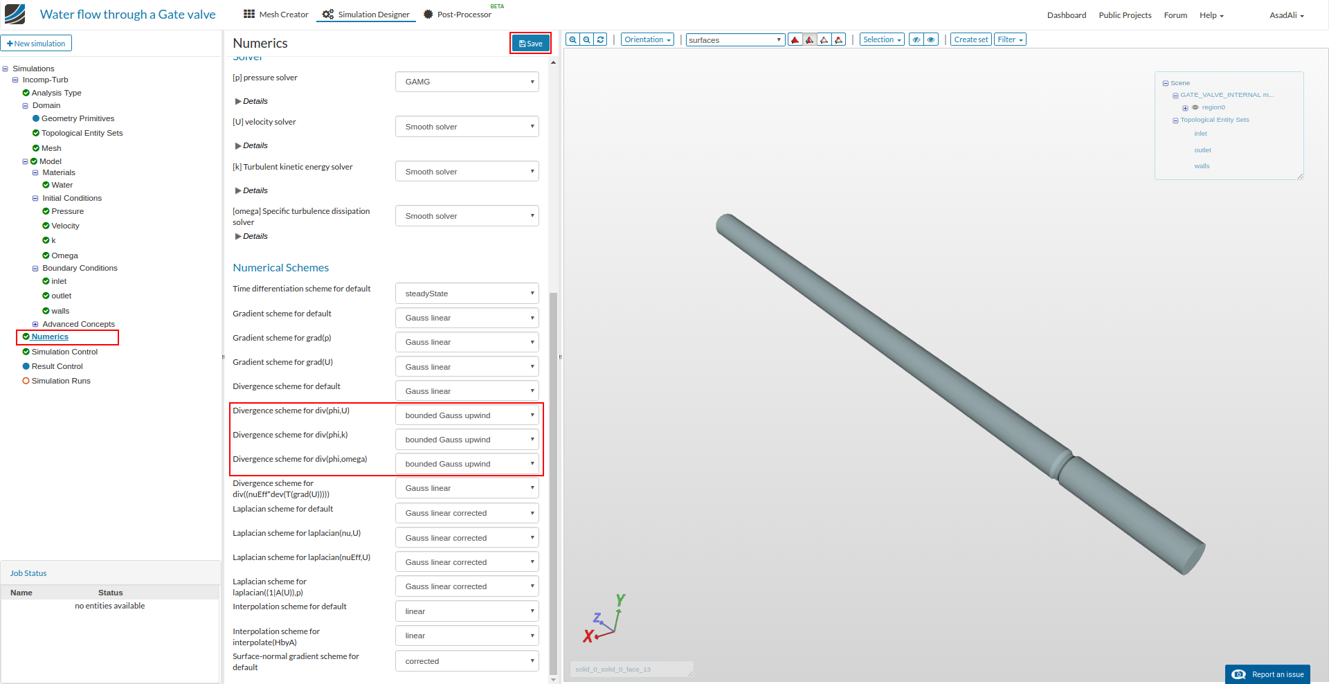
Now to set the solver parameters, move to the Numerics and set the parameters according to the images below. Save the selection.
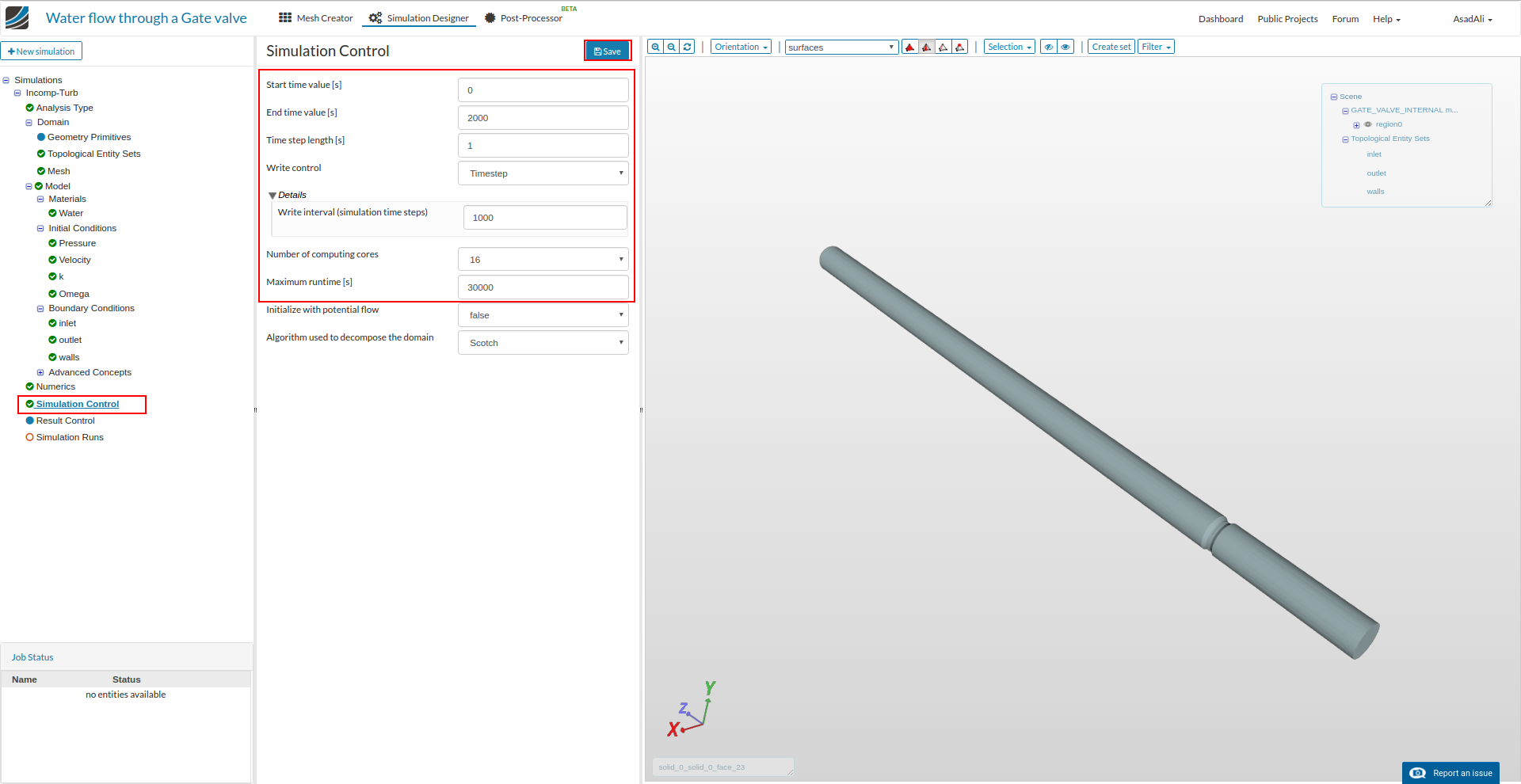
Now move to the Simulation Control and set the parameters. Save the selection.
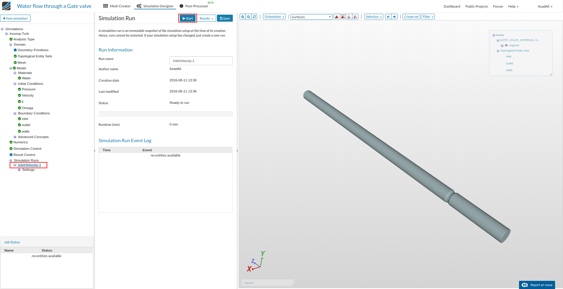
Now move to the Simulation Runs and add a new simulation run. Once simulation run is created press Start to start the simulation.
 I will tackle that and get back to you as soon as possible! Thanks