Recording
Homework Submission
Your homework is to investigate the Full car model FSAE Full Car with a radiator using the porous media approach, rotating wheels using the rotating wheel boundary condition, and rotation of the car rims using Multi Reference Frame (MRF). For this case, the front wing flap angle of 0 degrees will be considered and the velocity of the car will be set at a constant 20 m/s.
The step-by-step tutorial below contains all of the steps for setting up the simulation in SimScale and visualizing the results.
We’ve made an update to the platform and the sharing procedure has changed. Please go to the following link to see how to get a sharing link for your project:
New Sharing on SimScale
Homework Deadline: October 3rd, 11:59 pm CEST
Click Here to Submit your Homework
Outline
Part 1:
-
Introduction
-
Project Import
-
Mesh Generation
a. Geometry Primitives
b. Mesh Refinements
c. Start Operation -
Simulation Setup (Part 1)
a. Analysis Type
b. Domain
c. Material
d. Initial Conditions
e. Boundary Conditions
Part 2:
-
Simulation Setup (Part 2)
a. Advanced Concepts
b. Numerics
c. Simulation Control
d. Result Control
e. Simulation Runs -
Post Processing on SimScale
-
Homework Link
-
Result Analysis
a. Highlights
b. Porous Media vs No Porous Media
c. MRF vs No MRF
Introduction
This is part one of the step-by-step tutorial. In this part you will be guided through the meshing setup and part of the simulation setup. In the second part you will be guided through the last steps of the simulation setup, the post-processing of the results, and we will visualize and analyze some results.
Your task is to investigate the Full car model FSAE Full Car with a radiator using the porous media approach, rotating wheels using the rotating wheel boundary condition, and rotation of the car rims using Multi Reference Frame (MRF).
For this case, the front wing flap angel of 0 degrees will be considered and the velocity of the car will be set at a constant 20 m/s.
Let’s take a look at the physics of the full car before we start to set up our simulations:

As a first simplification we can exploit the symmetry of the car. Simulating only one half of the car reduces the computational effort by defining the inner surrounding wall (brown) as a symmetry plane.
The body of the car is a physical wall (grey), which means that it involves friction and should be defined as so-called “non-slip walls”.
The outer (not visible here) and upper surrounding walls (blue) are necessary to limit the size of the domain we want to simulate (we are not able to simulate an infinitely large domain). In reality, these walls do not exist and should not interact with the flow. A good approximation here is to assume this wall as frictionless or so-called “slip walls”.
There is no relative motion between the air and the floor. Thus, we will apply a wall velocity on the lower surrounding wall (cyan).
The bounding face on the right-hand side (red) will be defined as a inlet with a constant flow velocity profile.
The bounding face on the left-hand side (green) will be defined as a outlet with a constant pressure.
The tires (black) will be defined rotating by the help of a rotating boundary condition .
The rims (yellow) will be defined rotating by using Multi Reference Frame (MRF) zone.
Project Import
To start this exercise, please import the project into your workspace by clicking on the link below:
If the project appears to be private, please make a copy to be able to work on it.
Mesh Generation

In the Mesh Creator tab, click on the geometry FSAE Full Car and click on New Mesh to start creating a new mesh.
The new mesh operation will be generated automatically.
Next change:
-
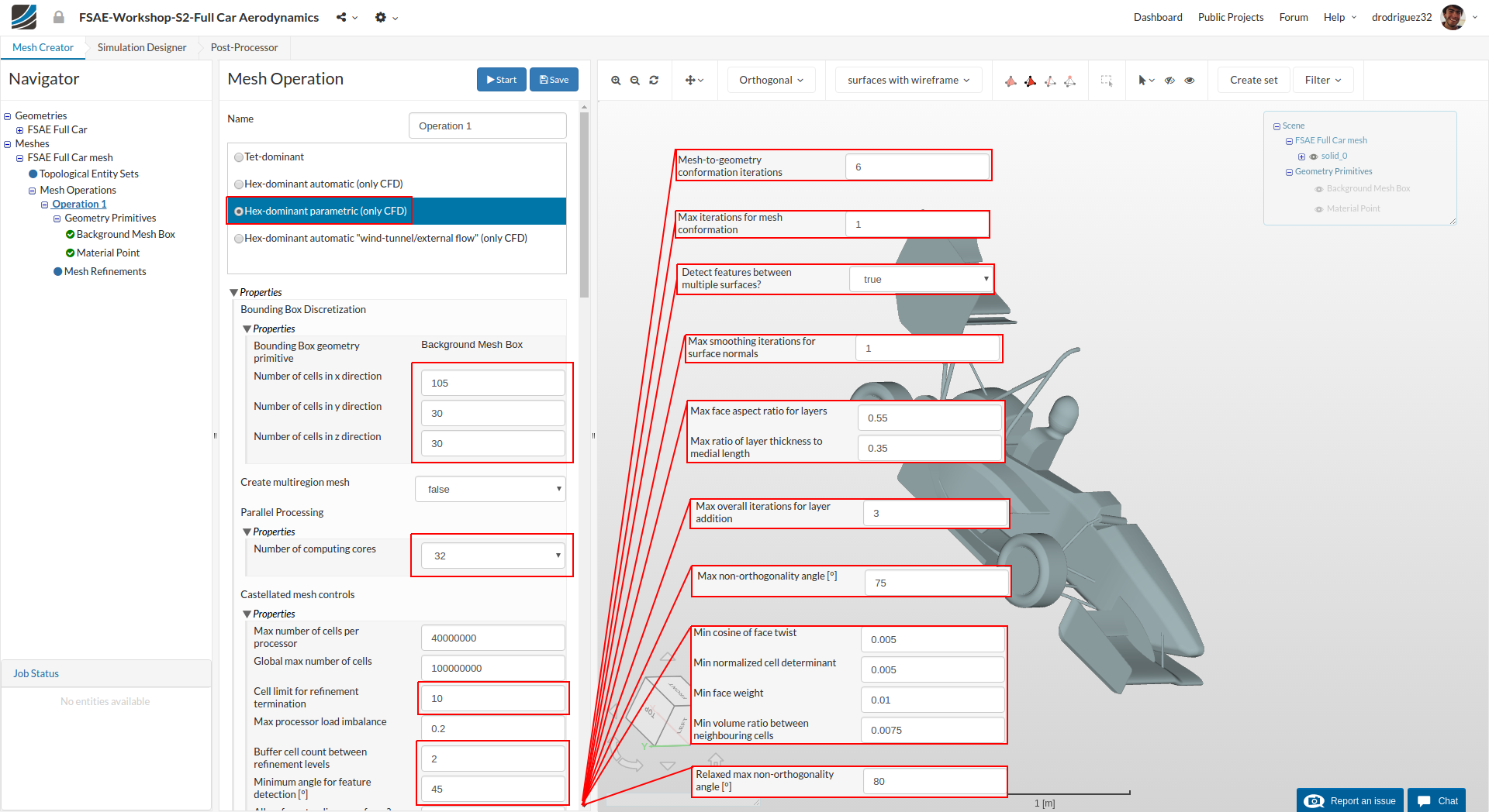
Type to Hex-dominant parametric (only CFD)
-
Bounding Box geometry primitive to the following:
Number of cells in x direction to 105
Number of cells in y direction to 30
Number of cells in z direction to 30 -
Number of parallel computing cores to 32 Scroll down to change other values to optimize the meshing parameters
-
Cell limit for refinement termination to 10
-
Buffer cell count between refinement levels and Minimum angle for feature detection [°] to 2 and 45 respectively
-
Mesh-to-geometry conformation iterations to 6 and Max iterations for mesh conformation to 1
-
Max smoothing iterations for surface normals [-] to 1
-
Detect features between multiple surfaces? to True
-
Max face aspect ratio for layers [-] and Max ratio of layer thickness to medial length [-] to 0.55 and 0.35 respectively
-
Max overall iterations for layer addition to 3
-
Max non-orthogonality angle to 75
-
Min cosine for face twist, Min normalized cell determinant,Min face weight and Min volume ratio between neighbouring cells to 0.005, 0.005, 0.01 and 0.0075 respectively
-
Relaxed max non-orthogonality angle to 80
-
Click Save to register changes.
Geometry Primitves
Background Mesh Box
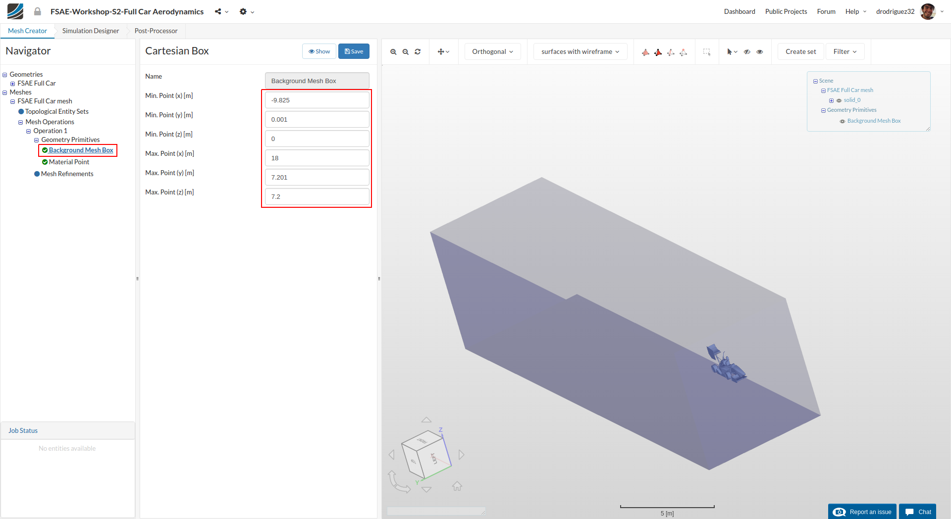
Go to Background Mesh Box under Geometry Primitives and change the mesh box dimensions:
Min. Point (x) = - 9.825
Min. Point (y) = .001
Min. Point (z) = 0
Max. Point (x) = 18
Max. Point (y) = 7.201
Max. Point (z) = 7.2
Click Save to save the changes. Click on reset icon over viewer to see the created mesh box in viewer.
MaterialPoint
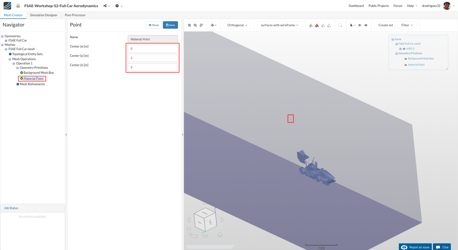
Go to MaterialPoint and change the values to the following:
Center (x) = 0
Center (y) = 2
Center (z) = 5
Then click Save
As we explained in the past tutorial, the material point tells the meshing algorithm whether to generate an outside mesh or an inside mesh. Here we want an external flow simulation, so the point should be on the outside of the car (and inside of the Background Mesh Box).
Cartesian Box - Lower
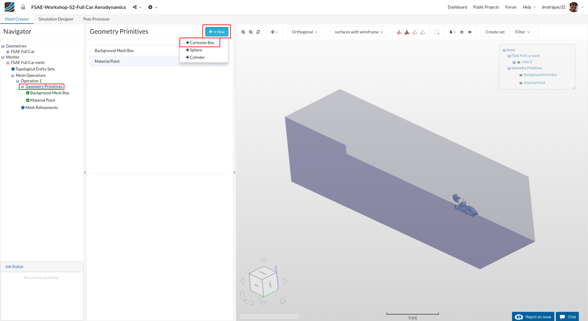
Next go back to the Geometry Primitives and click on +New and then Cartesian Box to define a new Cartesian box that will be used to define a mesh refinement region.
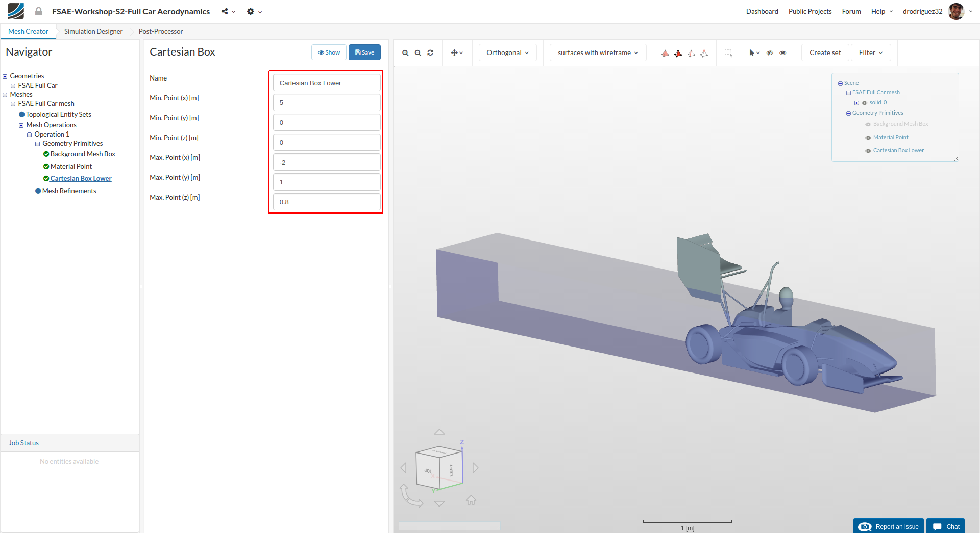
After creating a new Cartesian Box, you will be directed to the definition of this Cartesian Box. Rename it to Cartesian Box-lower (optional) and change the dimensions of the box to the following:
Min. Point (x) = 5
Min. Point (y) = 0
Min. Point (z) = 0
Max. Point (x) = - 2
Max. Point (y) = 1
Max. Point (z) = .8
This box will be refined later in the process and it will allow us to get better results and observe with more detail the flow around the car and directly in its wake.
Click Save to register your changes.
Cartesian Box - Upper
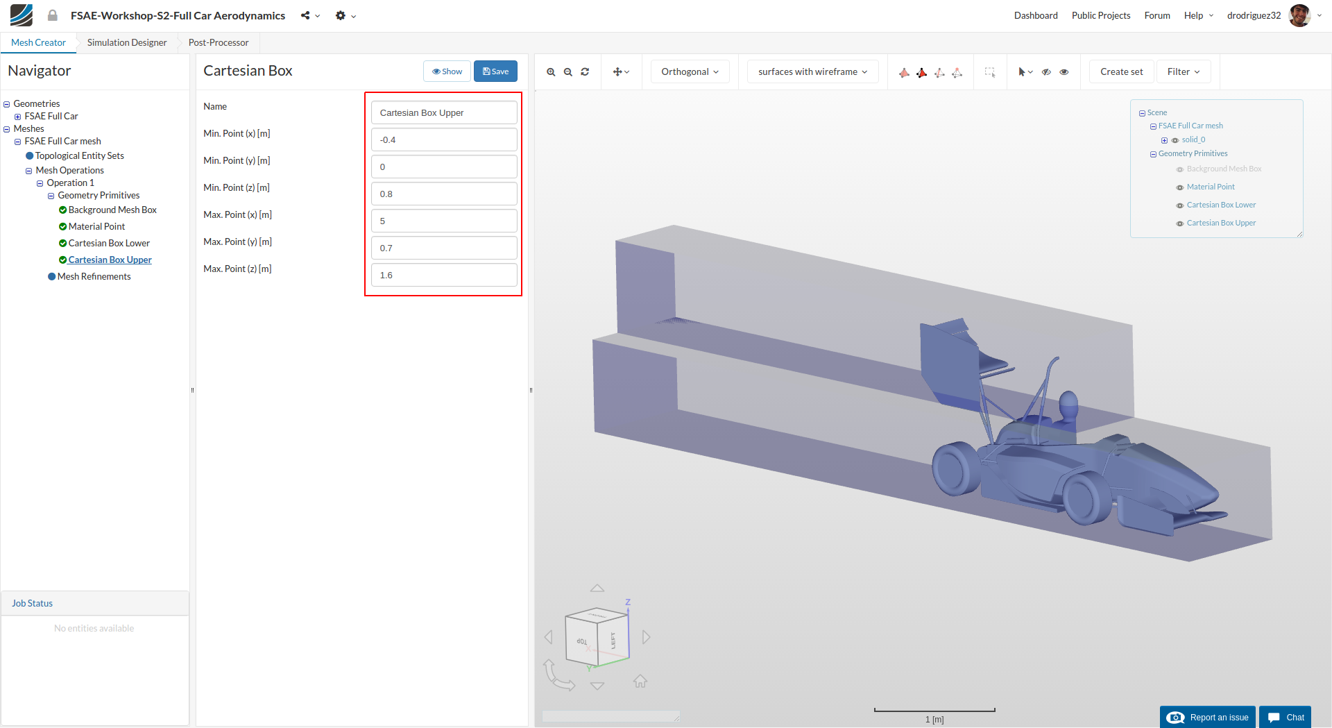
Create another Cartesian Box for further refinement definitions and rename it to Cartesian Box-upper (optional). This time change the values to the following:
Min. Point (x) = - 0.4
Min. Point (y) = 0
Min. Point (z) = 0.8
Max. Point (x) = 5
Max. Point (y) = 0.7
Max. Point (z) = 1.6
Like the past one, this will also be refined and allow us to get better results around the back wing and better observe its wake.
Click Save to register your changes.
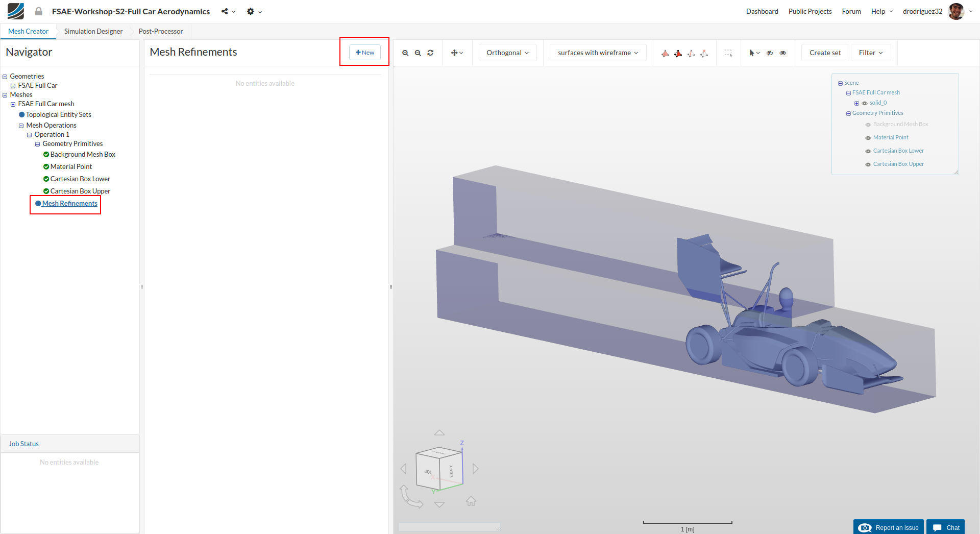
Mesh Refinements
A good mesh requires well defined refinements. Now we will start creating the mesh refinements. For this proceed to Mesh Refinements and click +New
Mesh Refinement 1 - Surface
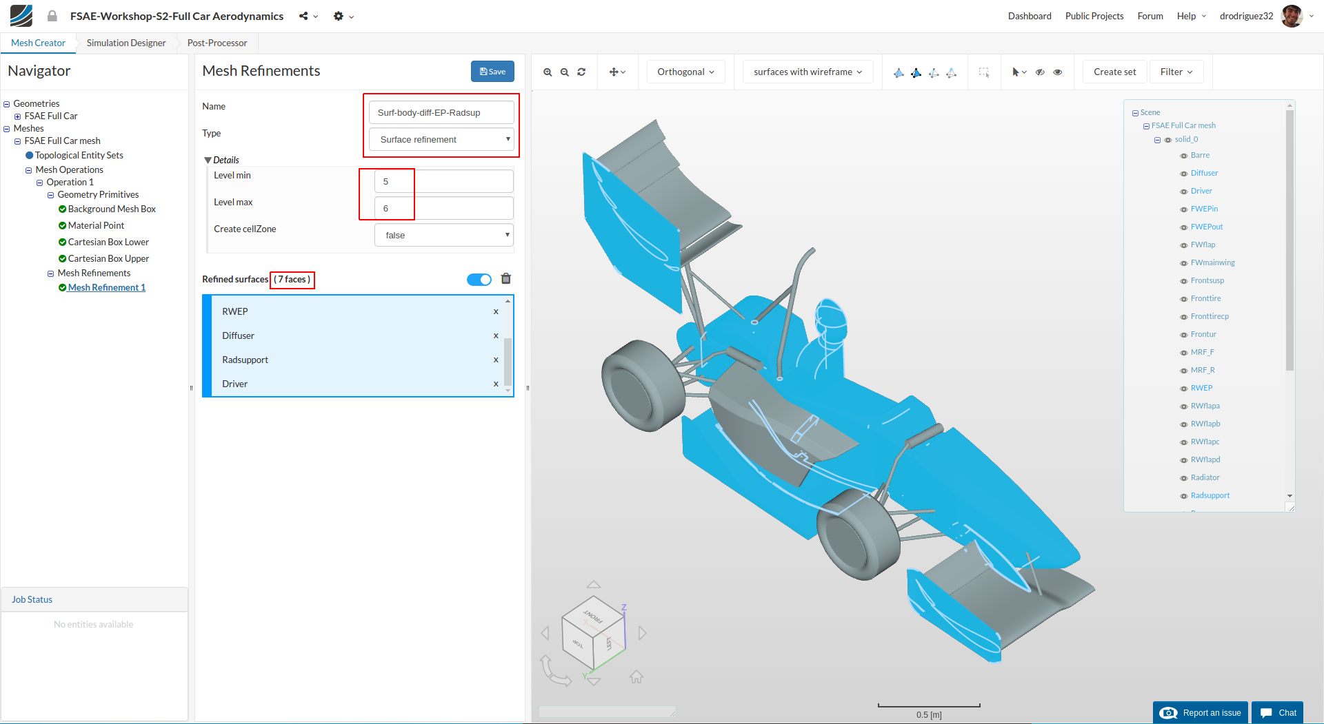
A new mesh refinement will be created. Rename it to Surf-body-diff-EP-Radsup (optional).
Change the Type to Surface refinement and change Level min and Level max to 5 and 6 respectively.
From the navigator in the right select body, FWEPin (Front Wing Inner Endplate), FWEPout (Front Wing Outer Endplate), RWEP (Rear Wing Endplate), Diffuser, Radsupport and Driver
You should see those faces under Refined surfaces (7 faces) and they should be highlighted in blue.
Click Save to register your changes.
Mesh Refinement 2 - Surface
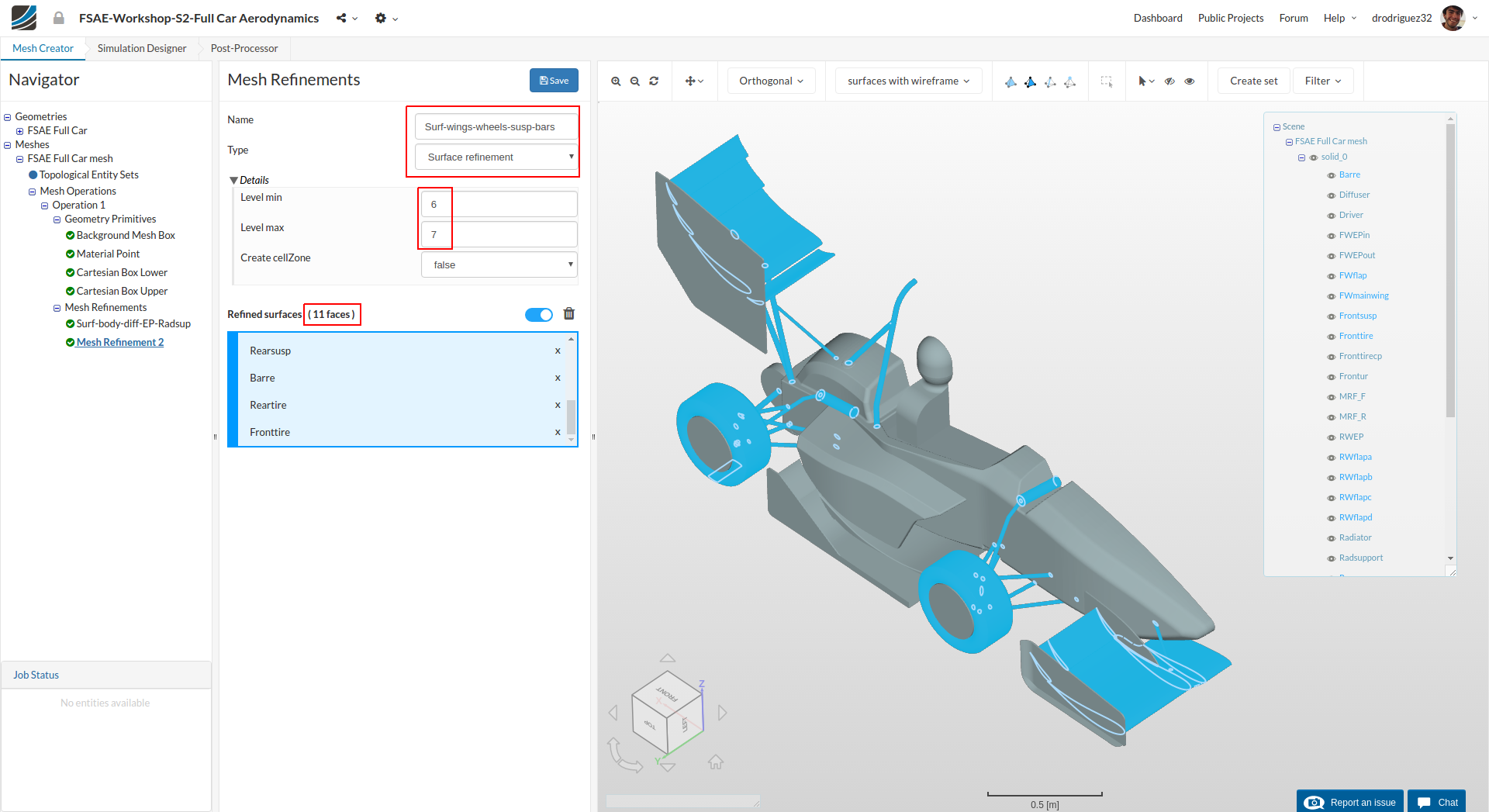
Create a new mesh refinement and rename it to Surf-wings-wheels-susp-bars (optional).
Change the Type to Surface refinement and change Level min and Level max to 6 and 7 respectively.
From the navigator in the right select FWmainwing, FWflap, RWflapa, RWflapb, RWflapc, RWflapd, Frontsusp, Rearsusp, Barre, Reartire and Fronttire.
You should see those faces under Refined surfaces (11 faces) and they should be highlighted in blue.
Click Save to register your changes.
Mesh Refinement 3 - Surface
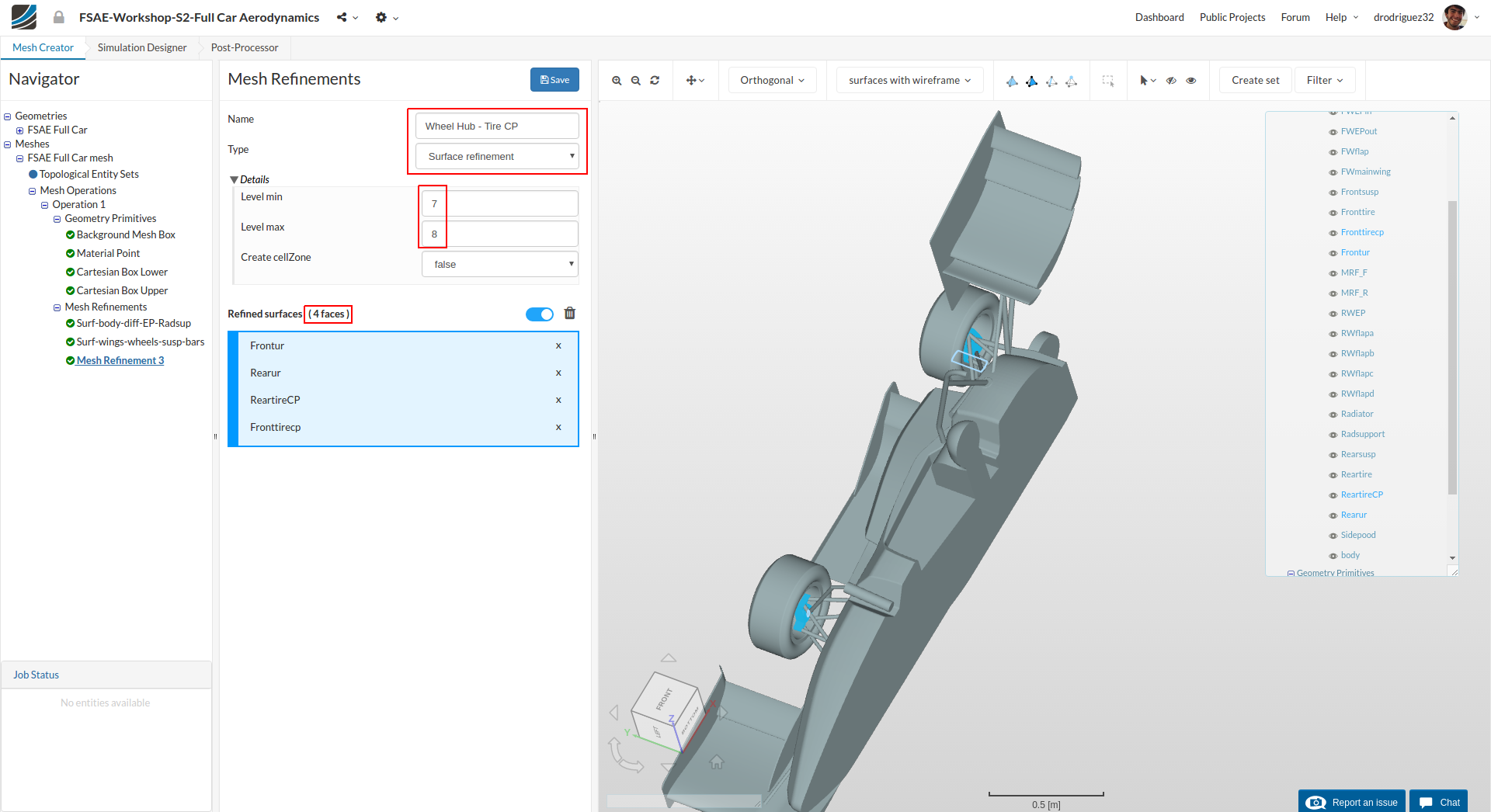
Create a new mesh refinement and rename it to Wheel Hub - Tire CP (optional).
Change the Type to Surface refinement and change Level min and Level max to 7 and 8 respectively.
From the navigator in the right select Frontur, Rearur, ReartireCP and Fronttirecp
You should see those faces under Refined surfaces (4 faces) and they should be highlighted in blue.
Click Save to register your changes.
Mesh Refinement 4 - Surface
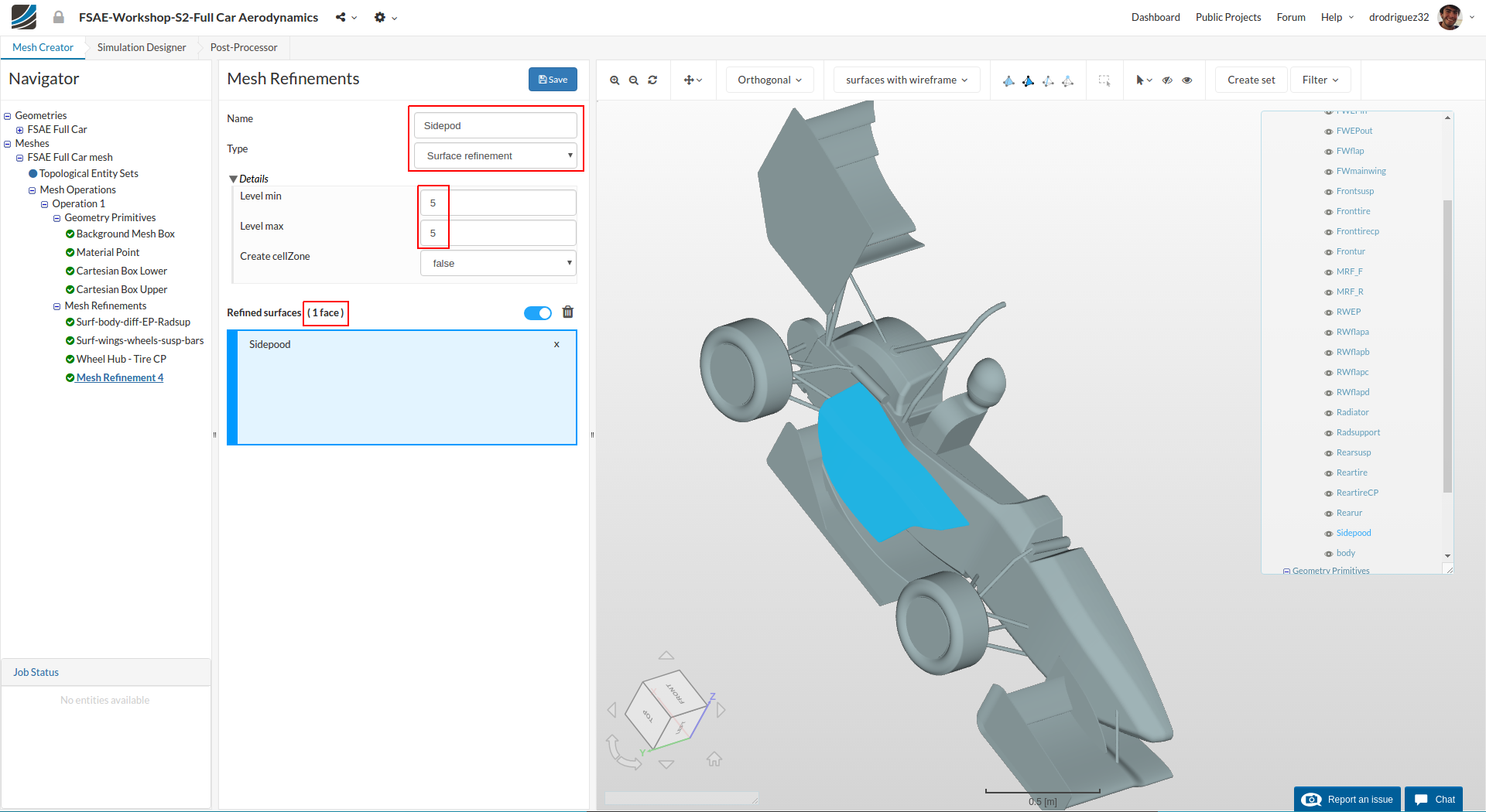
Create a new mesh refinement and rename it to Sidepod (optional).
Change Type to Surface refinement and change Level min and Level max to 5 and 5 respectively.
From the navigator in the right select Sidepod
You should see the face under Refined surfaces (1 face) and it should be highlighted in blue.
Click Save to register your changes.
Mesh Refinement 5 - Surface
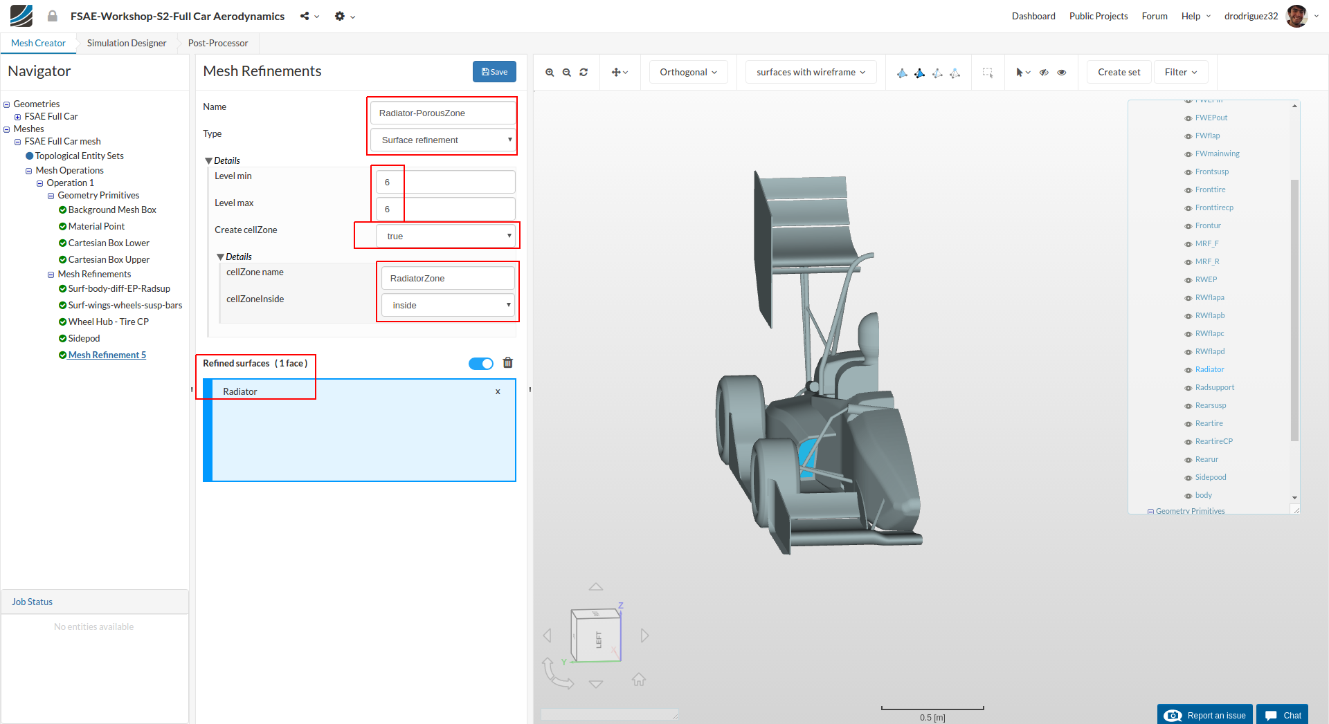
Create a new mesh refinement and rename it to Radiator-PorousZone (optional).
Change Type to Surface refinement and change Level min and Level max to 6 and 6 respectively.
Change Create cellZone to true and rename cellZone name to RadiatorZone
From the navigator in the right select Radiator
You should see the face under Refined surfaces (1 face) and it should be highlighted in blue.
Click Save to register your changes.
Mesh Refinement 6 - Feature
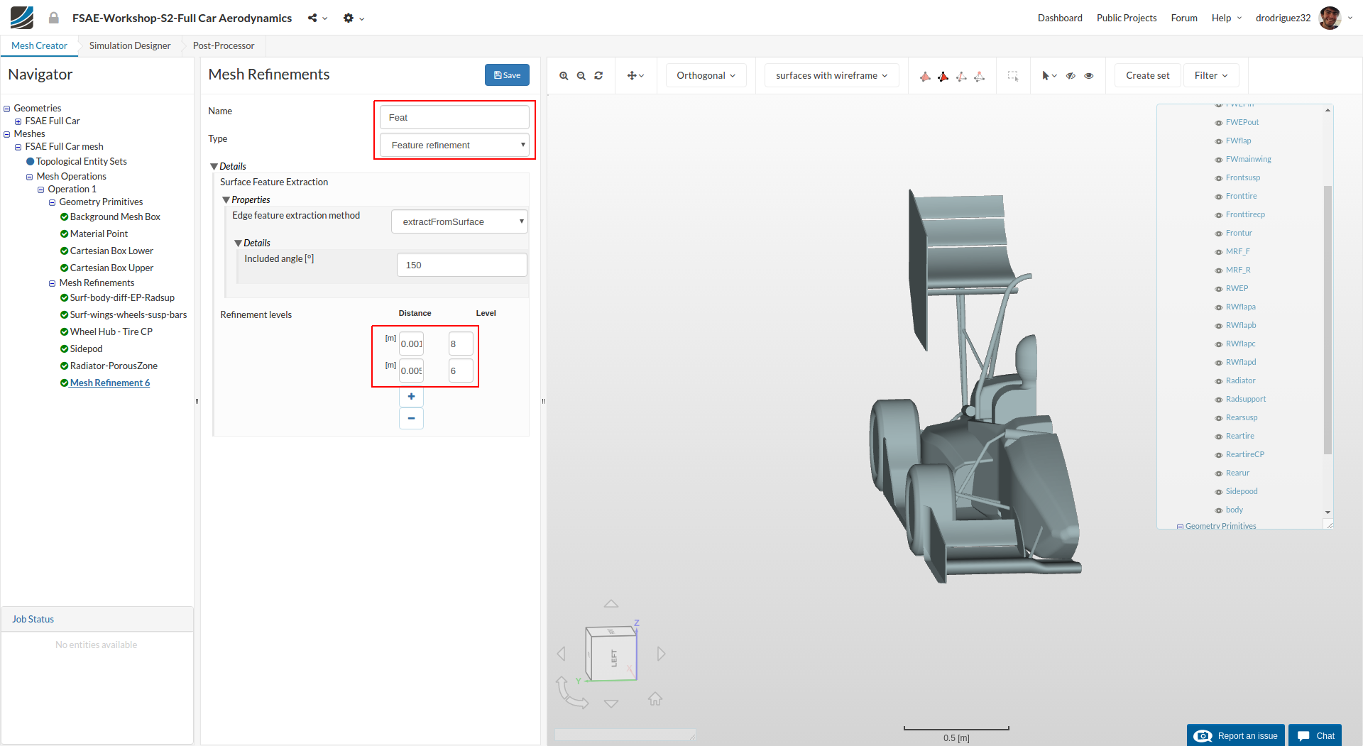
In order to create a separate feature refinement for small features, create a new mesh refinement and rename it to Feat (optional).
Change Type to Feature refinement and then click + button to add an extra value. In the first row, change Distance and Level value to 0.0015 and 8 respectively. Similarly, change the value to 0.005 and 6 in second row.
Click Save to save the feature refinement.
Mesh Refinement 7 - Region
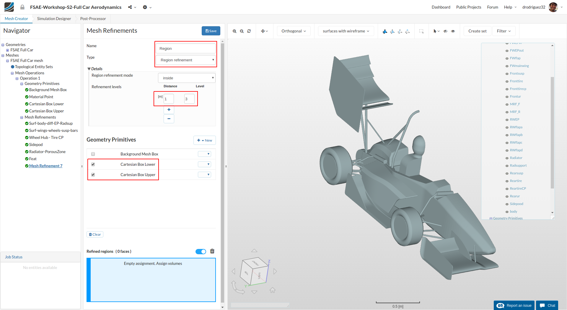
In order to define the refinement level for the created Cartesian boxes, create a new mesh refinement and rename it to Region (optional).
Change the Type to Region refinement and then change Feature refinements levels Level to 3. Select Cartesian Box-inner and Cartesian Box-outer under Geometry Primitives
Click Save to register the refinements for the specific Cartesian Boxes.
Mesh Refinement 8 - Boundary Layer
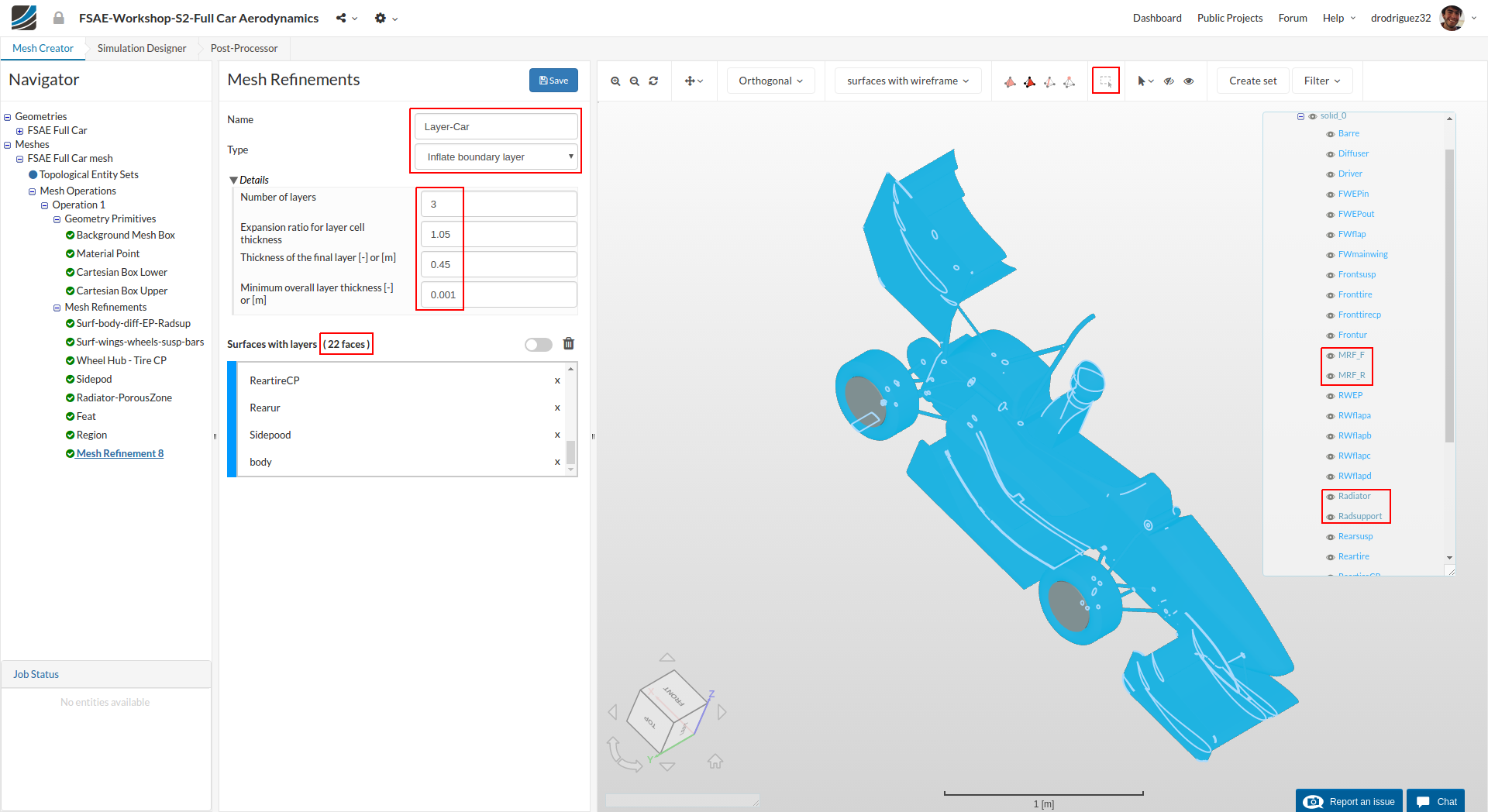
Next we will define the boundary layers over car surfaces in order to have a uniform layer refinements. Layers will allow us to accurately capture and observe the flow behavior close to the surface of the car.
Create a new refinement and rename it to Layer-Car (optional).
Change the Type to Inflate boundary layer and further change Number of layers [-], Expansion ratio for layer cell thickness [-], Thickness of the final layer [-] and Minimum overall layer thickness [-] to 3 , 1.05, 0.45 and 0.001 respectively.
Select all the faces except Radiator; Radsupport, MRF_F and MRF_R. You can do this by clicking on the box selector option in the toolbar, drawing a box over the whole car (which will select all the faces) and then unselect the faces mentioned before using the navigator on the right.
Click Save to register your changes.
Mesh Refinement 9 - Boundary Layer
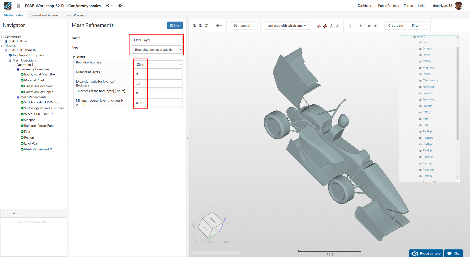
For the floor layers, create a new refinement and rename it to Floor-layer (optional).
Change the Type to Boundary box layer addition
Change Bounding box face to Zmin and then the Number of layers and Minimum overall layer thickness [-] to 3 and 0.001 respectively.
Click Save to register your changes.
Mesh Refinement 10 - Rotating Zone
Now, we will create a mesh refinement for additional MRF zones.
MRF refers to Multi Reference Frame. It’s a method commonly used for simulating parts that are in rotation because it’s computationally less demanding than other methods (like AMI). This approach adds Coriolis forces to the governing equations of cells in that zone so that the rotation can be simulated. MRF is a steady state approach (this is why it’s computationally less demanding), and this means that the effects of the rotating parts on the flow are approximated at a specific time. You can read more about rotating media in the SimScale Documentation (Rotating zones).
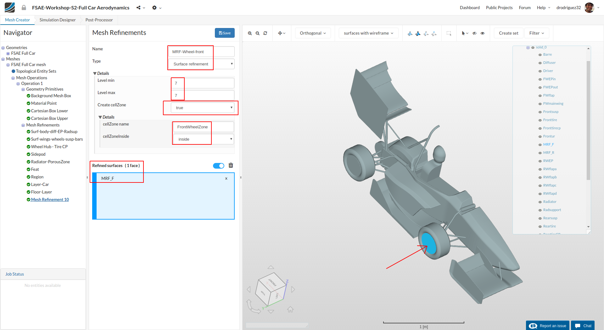
Create a new refinement and rename it to MRF-Wheel-front (optional).
Change the Type to Surface refinement and change both Level min and Level max to 7 respectively.
Change Create cellZone to true and rename cellZone name to FrontWheelZone
Select MRF_F
Click Save to register your changes.
Mesh Refinement 11 - Rotating Zone

Similarly, for the rear MRF create a new mesh refinement and rename it to MRF-Wheel-Rear (optional).
Change the Type to Surface refinement and change both Level min and Level max to 7 respectively.
Change Create cellZone to true and rename cellZone name to RearWheelZone
Select MRF_R
Click Save to register your changes.
Start Mesh Operation
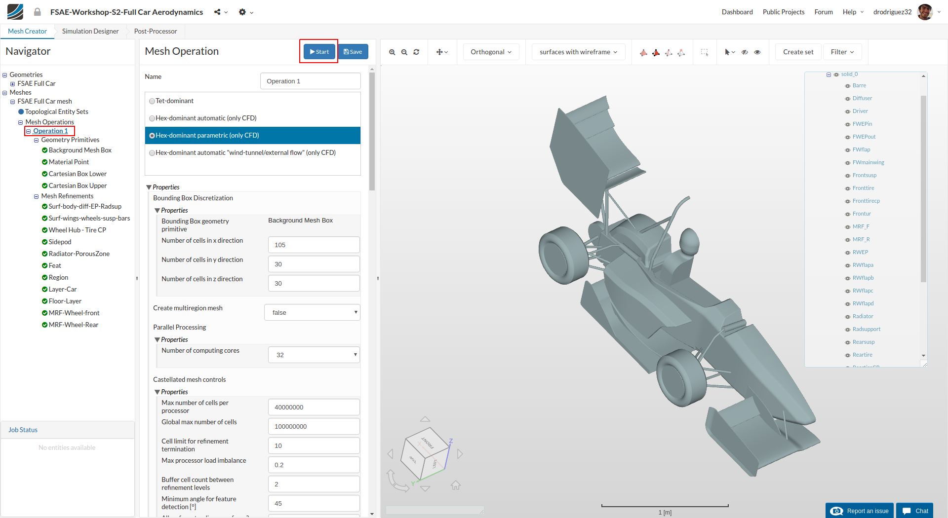
Once you have defined all of the mesh refinements, go back to the Operation 1 and click Start in order to submit the meshing job to the server. Due to the fineness of the mesh, the meshing could take 15 to 20 minutes to finish.
If you finished your meshing before September 25 please go back to the first step of the meshing process and make sure your settings are the same as in the text and the picture. If something is different, please re-run the meshing process as an update has been made to make sure you get a better mesh.
Simulation Setup (Part 1)
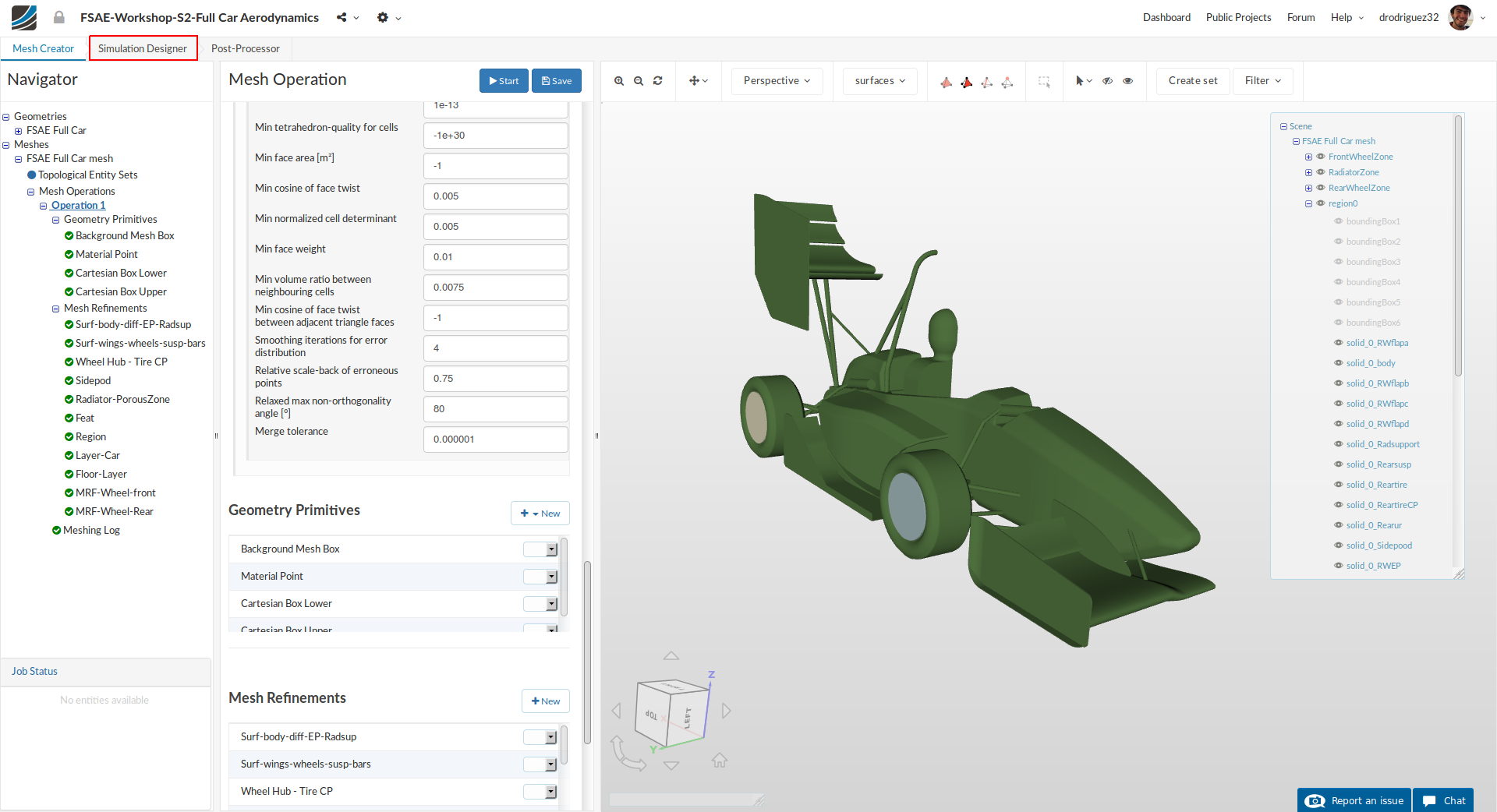
Once the meshing of the first geometry i.e. FSAE Full Car mesh is finished, you can proceed to Simulation Designer
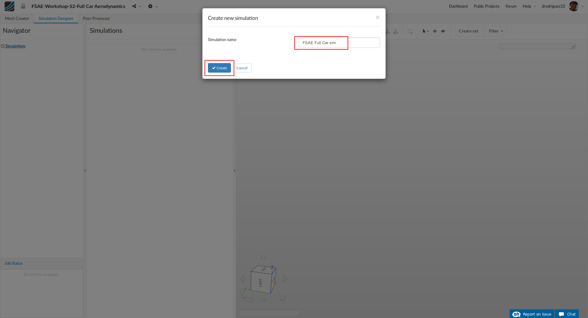
Once you are in Simulation Designer, click New Simulation in order to start setting up the simulation. A new simulation window will pop up. Rename it to FSAE Full Car sim (optional) and click Create in order to create a new simulation.
Analysis type
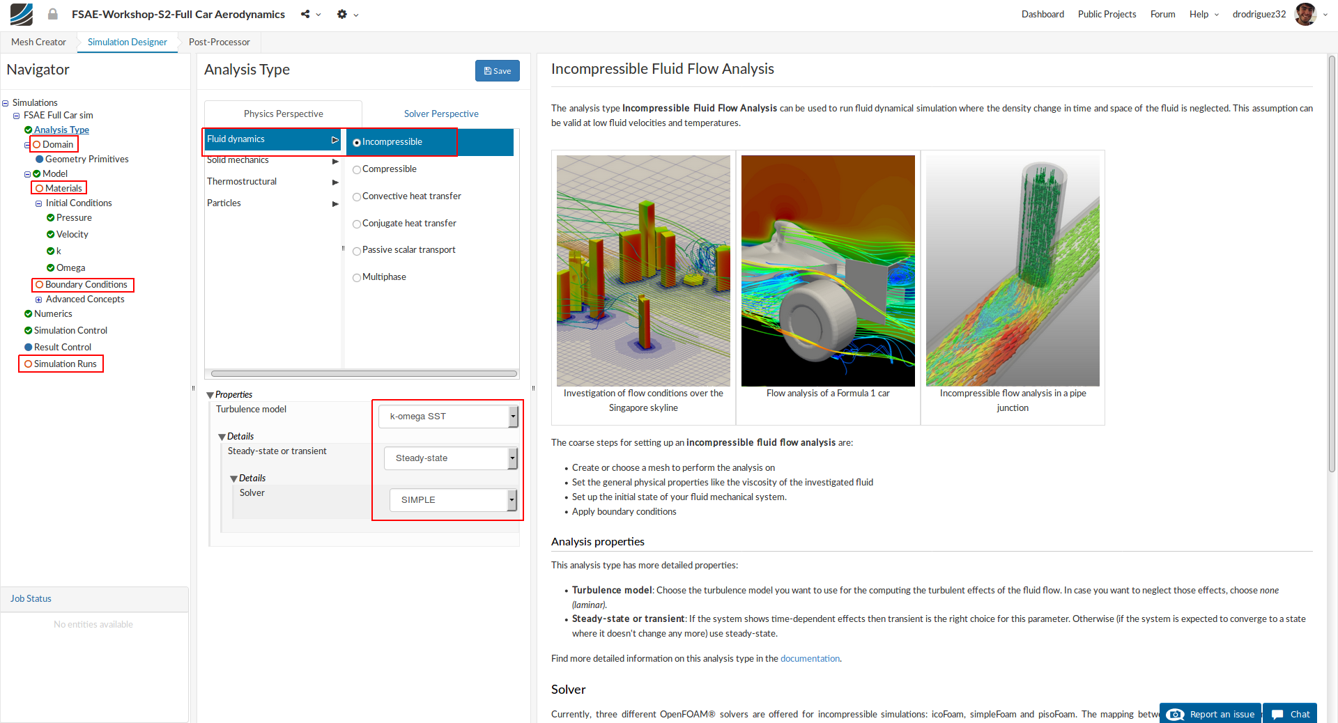
In Analysis Type, switch to Fluid dynamics and then select Incompressible. You don’t have to change any properties here. Just click Save to select this analysis type.
Once you save the analysis type, you will see the expanded tree. All the red entities show that they must be set up in order to perform a successful simulation run.
Domain

Next you have to select a domain on which this simulation will be performed. Proceed to Domain and select FSAE Full Car mesh and click Save. After a while you will see the loaded mesh of the selected domain in the viewer. For the easier mesh handling, it is recommended to switch to surfaces render mode in the top viewer bar
Material
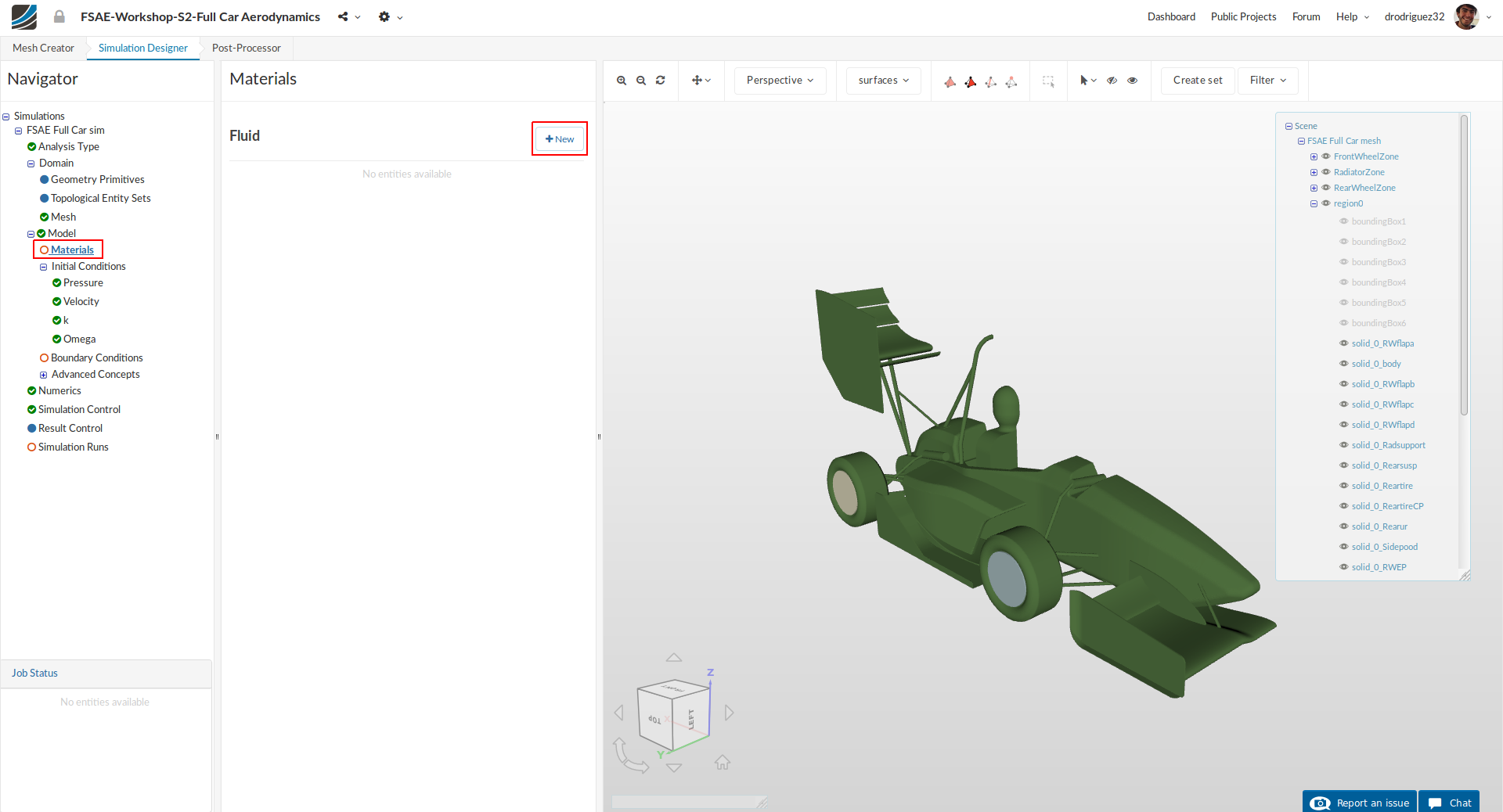
Next we have to define the fluid material. Go to Materials and click on New to create a new material.
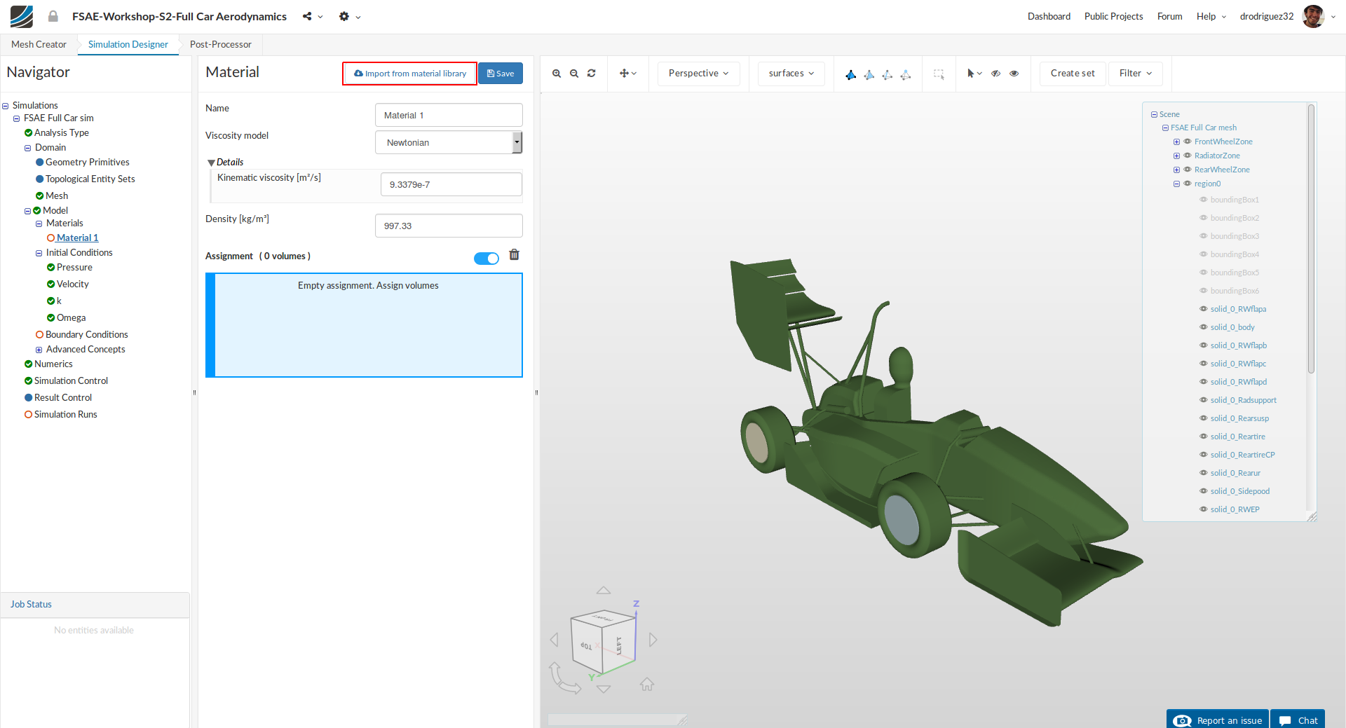
Click on Import from material library to import the desired material from the material database.
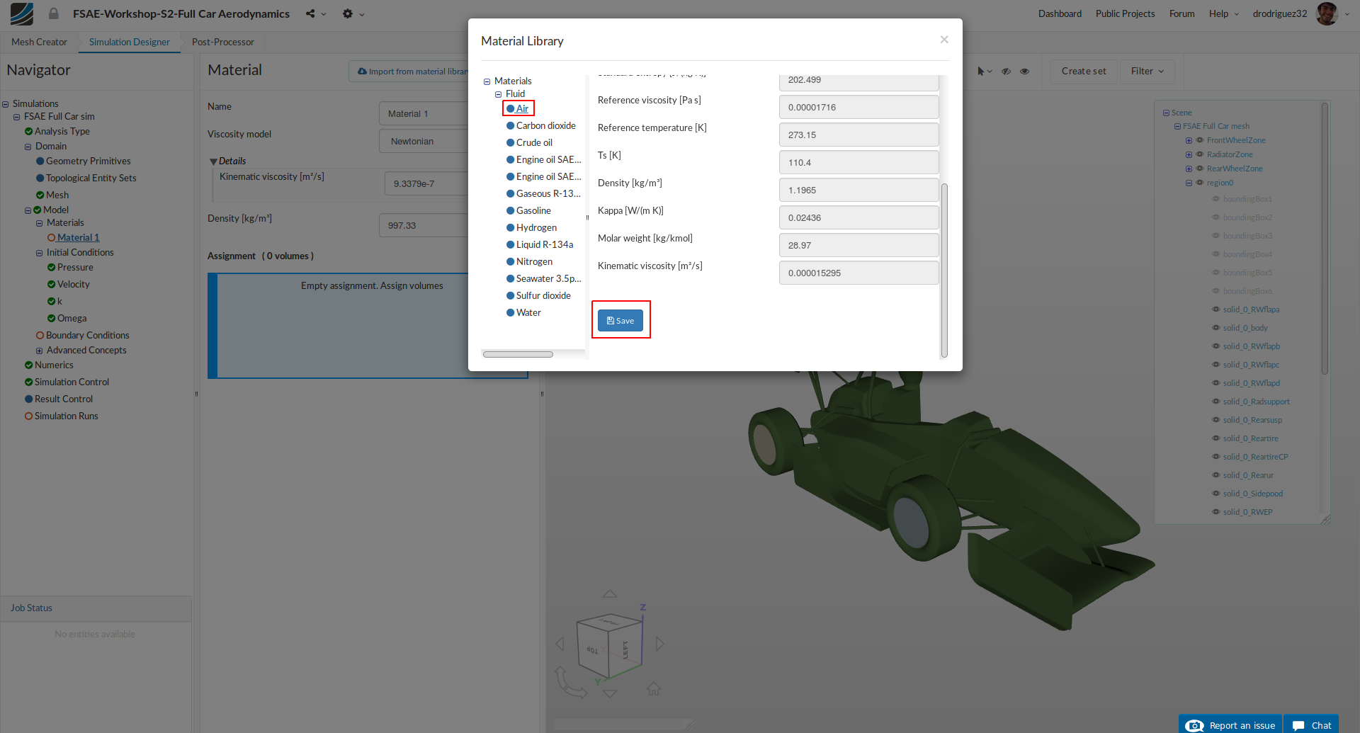
Select Air and click Save to import this material directly from the library.
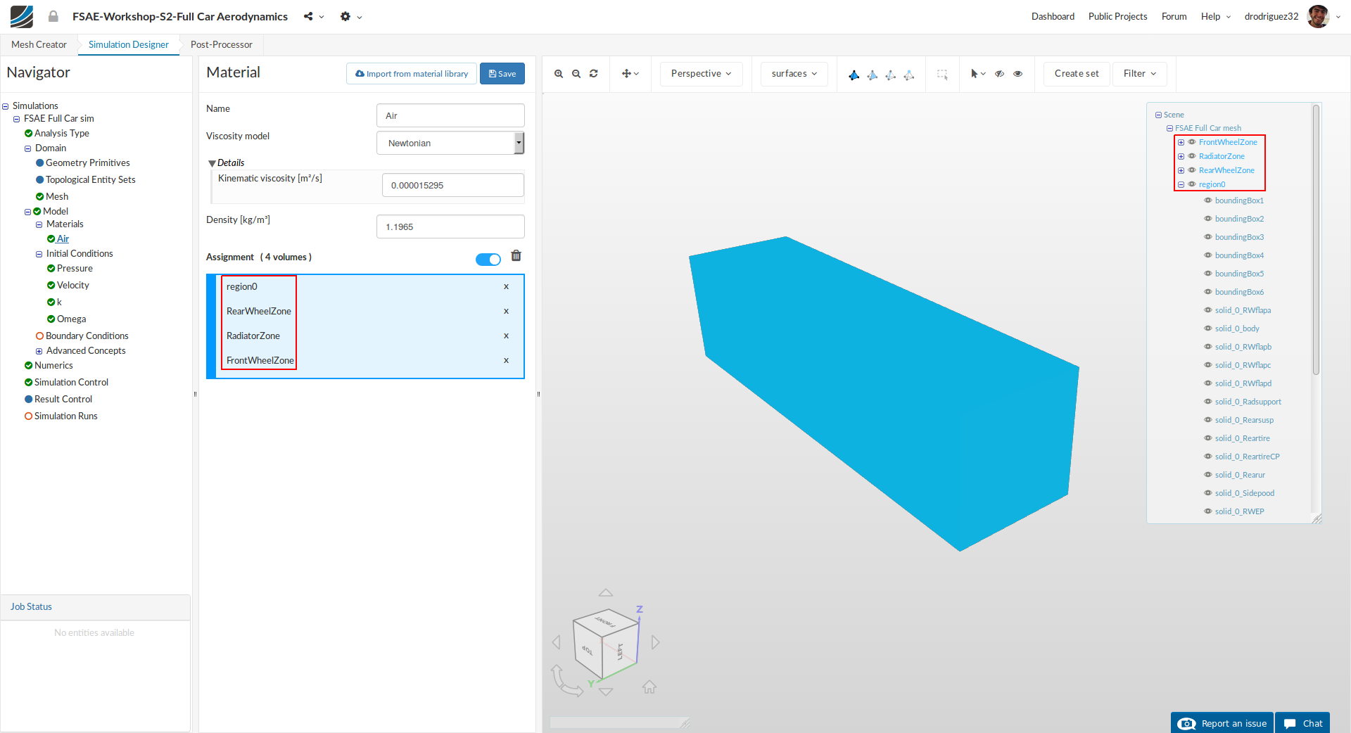
Select region0, RadiatorZone, FrontWheelZone and RearWheelZone from the navigator in the right. You should see the list in the blue highlighted zone under Assignment.
Initial Conditions
We will now proceed to change the initial conditions. We will leave Pressure and Velocity with the defaults set by SimScale.

Go to k and change the Turbulent kinetic energy value [m²/s²] value to 0.06 and click Save.
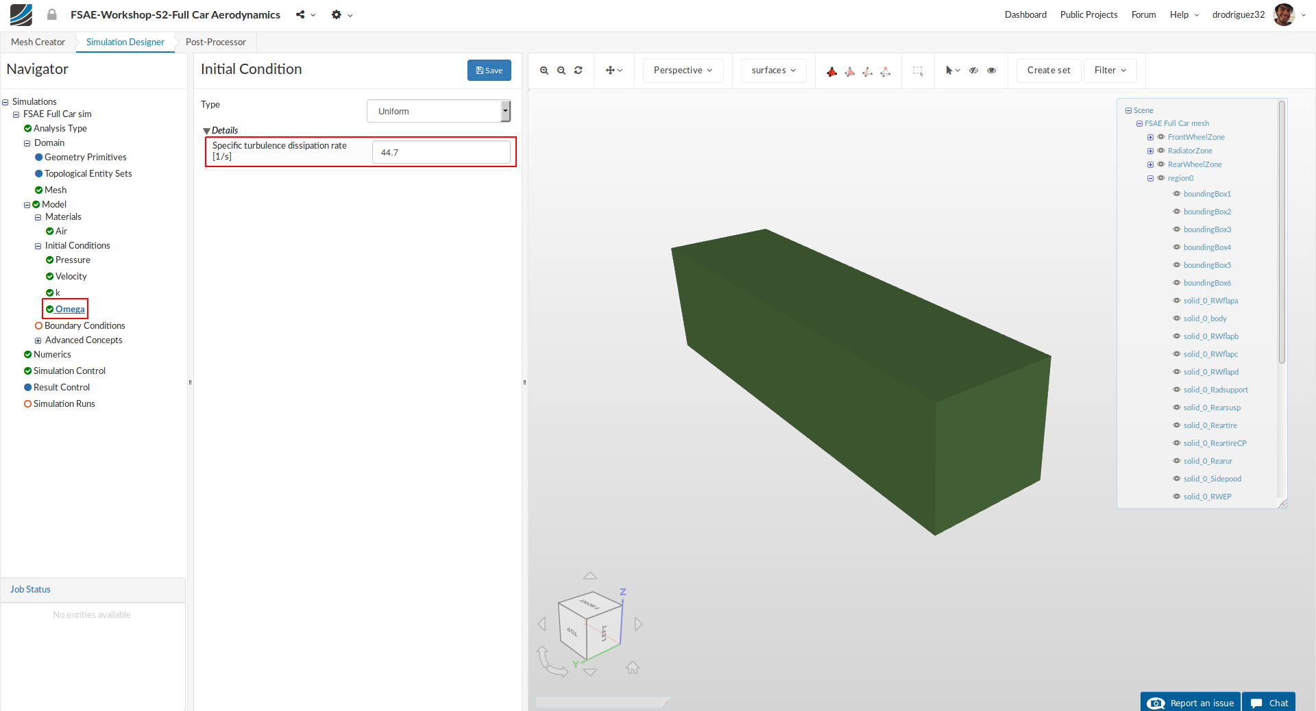
Next go to Omega and change Specific turbulence dissipation rate [1/s] to 44.7 and click Save.
As mentioned in the previous tutorial, the two settings you just modified are associated to the turbulence model that will be applied to this simulation (K-Omega SST). Turbulence is a highly complex process with irregular, chaotic, and unsteady 3D phenomenon. We would need an extremely fine mesh and a huge amount of computational power to correctly simulate it, so the standard process is to apply a model that mathematically predicts this turbulent behavior.
K (turbulent kinetic energy) refers to the kinetic energy associated with the turbulent flow and it is calculated by measuring the velocity fluctuations in the fluid and applying an RMS operation.
Omega (specific turbulence dissipation rate) is the rate at which the turbulent kinetic energy is turned into internal energy of the fluid. Its units match those of frequencies because it is also known as the frequency of the turbulence. This helps you visualize how long the turbulence lasts for.
Boundary Conditions
Now we will proceed to the most crucial and important section of the simulation setup: setting up the boundary conditions. This is simply telling the platform how we want the simulation to behave.
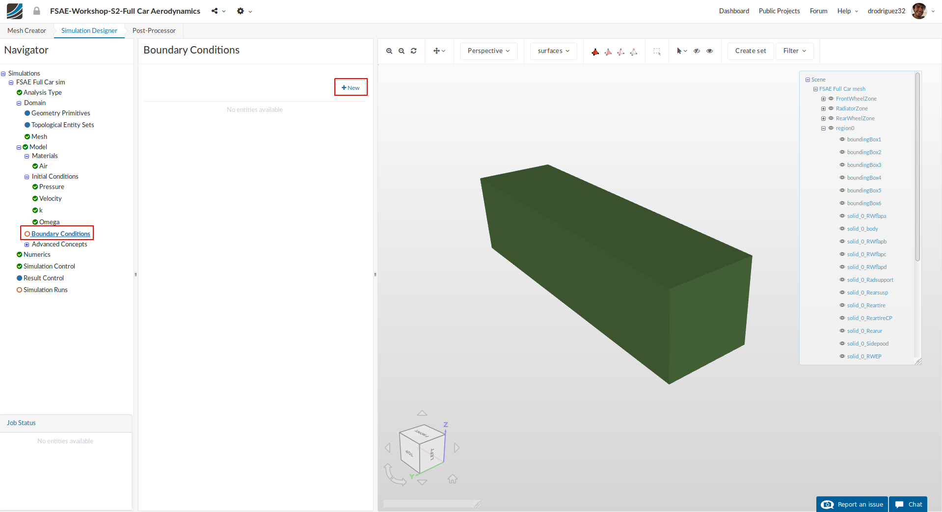
Go to Boundary Conditions and click +New in order to create a new boundary condition.
Inlet

Rename the newly created boundary condition to Inlet (optional).
Set the Type to Velocity Inlet
Change x value [m/s] of Velocity to 20
Select the face of the bounding box that is before the car (boundingBox3). You can do this by clicking on it or simply selecting it from the navigator in the right.
Click Save to define the inlet boundary condition.
Outlet
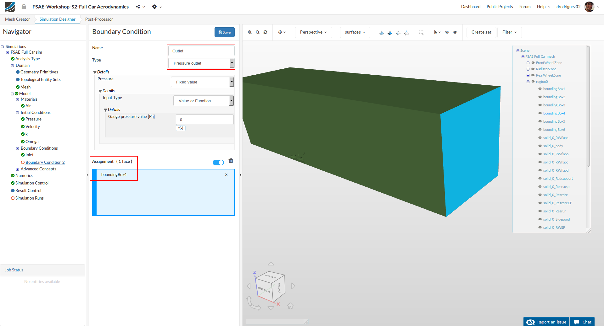
Create a new Boundary Condition and rename it to Outlet (optional).
Change the Type to Pressure Outlet
Select boundingBox4 (the back face of the bounding box) from the navigator on the right or by clicking on the face.
Click Save to define the outlet boundary condition.
Sides
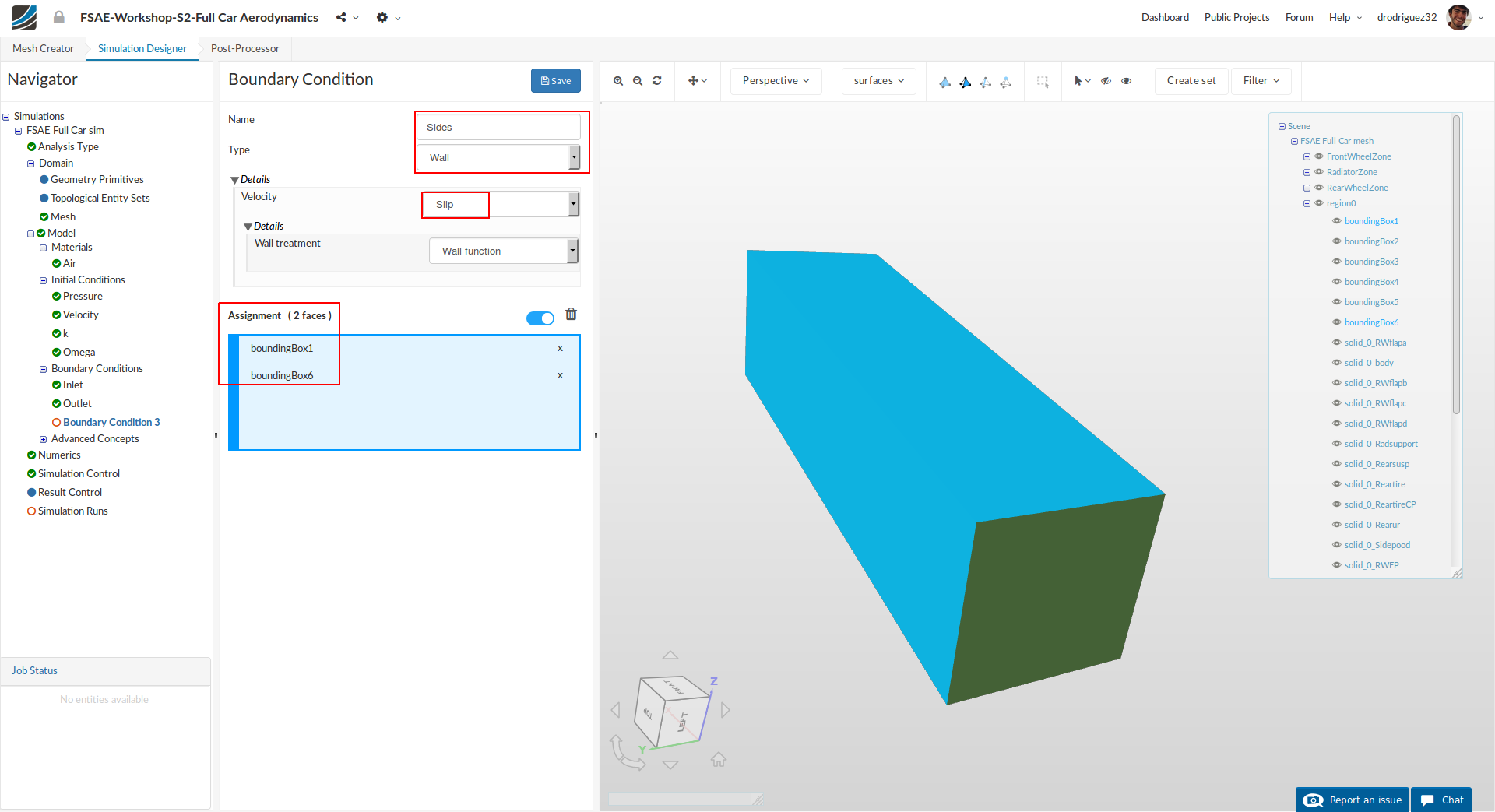
Create a new Boundary Condition and rename it to Sides (optional).
Change Type to Wall and Velocity to Slip.
Select boundingBox1 and boundingBox6 and click Save to define the boundary condition for the sides.
Remember to make sure the faces appear in the blue highlighted area titled Assignment.
Symmetry
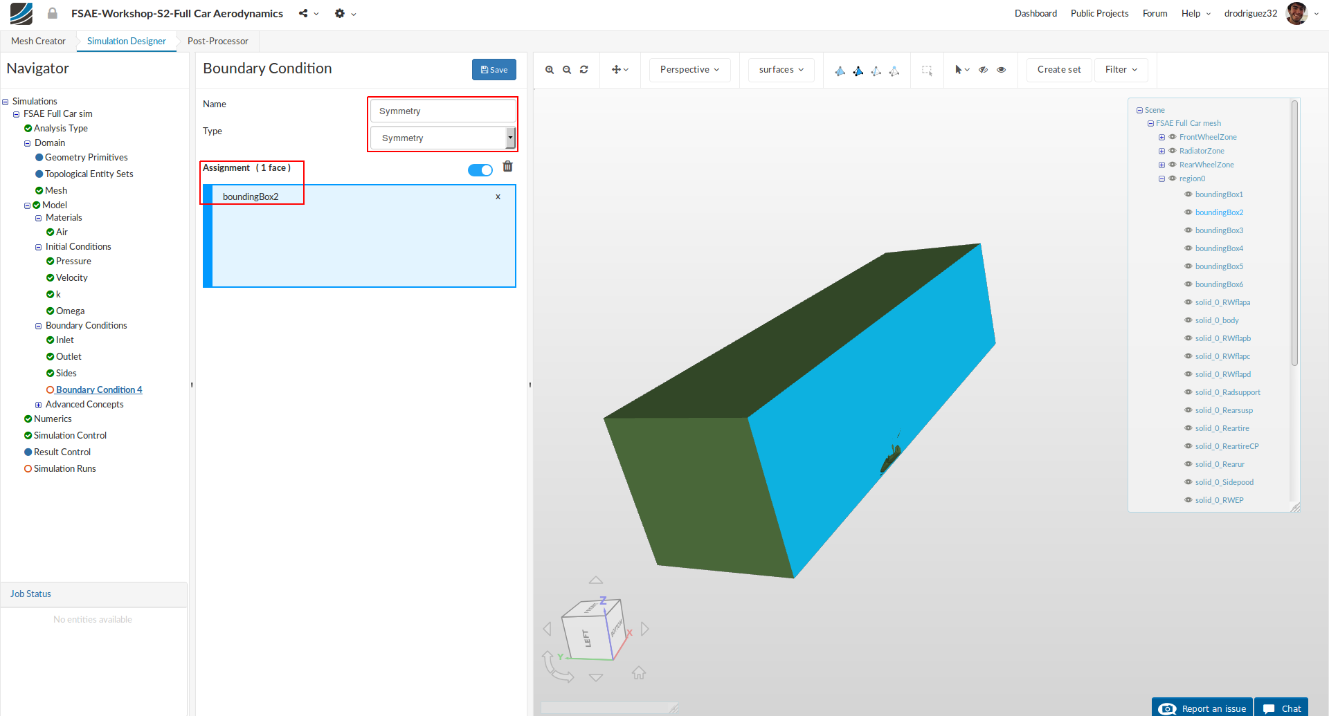
Create a new Boundary Condition and rename it to Symmetry (optional). This boundary condition is how the simulation algorithm knows that in reality we don’t have only half a car but a complete car, and so it assumes that what happens on one side will happen on the other.
Change the Type to Symmetry
Select boundingBox2 and click Save to define the symmetry boundary condition.
Floor
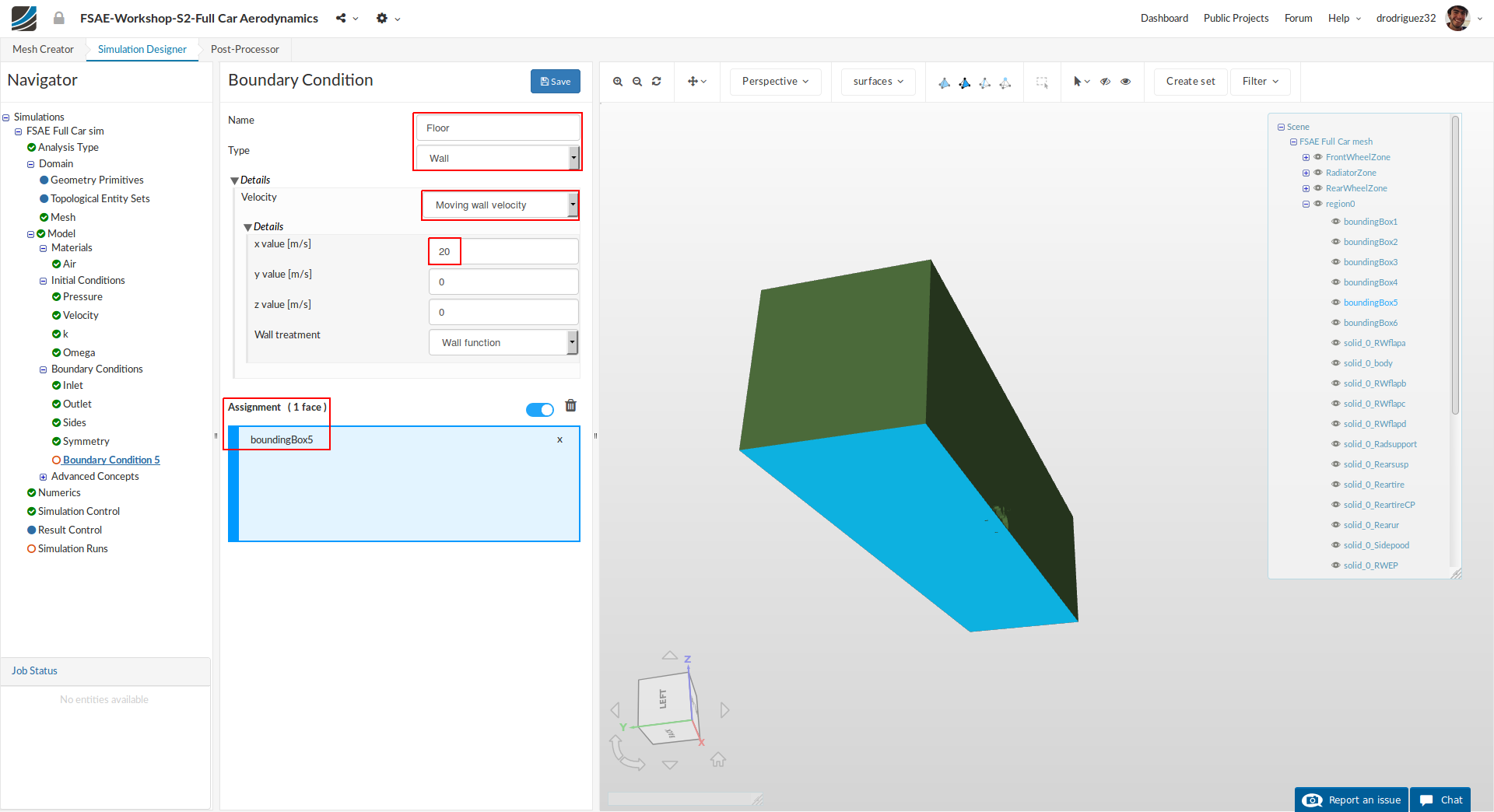
We will now define a moving floor boundary condition. Create a new boundary condition and rename it to Floor (optional).
Change Type to Wall, Velocity to Moving wall velocity and change x value [m/s] to 20
Select boundingBox5 and click Save to define the floor boundary condition.
Car
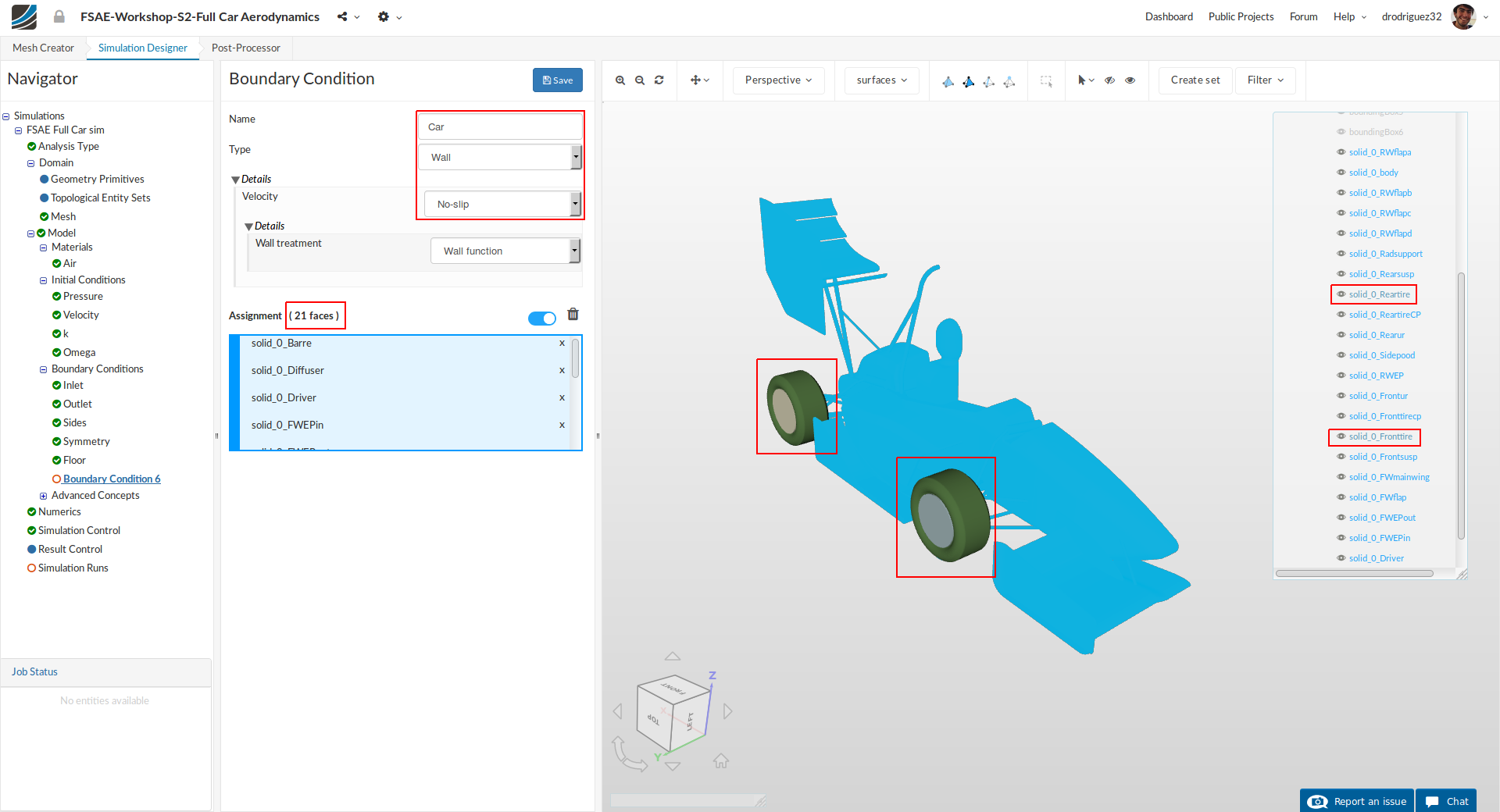
Now, we will define the boundary condition for the car. Create a new boundary condition and rename it to Car (optional).
Change the Type to Wall
Select all the entities starting with solid_0 EXCEPT solid_0_Reartire and solid_0_Fronttire from the navigator on the right.
Click Save to define the boundary condition for the car.
Rotating wheel (Front)
This is not the same thing as a Multi Reference Frame (MRF) zone. In part 2 of the tutorial we will begin with a detailed explanation of the difference.
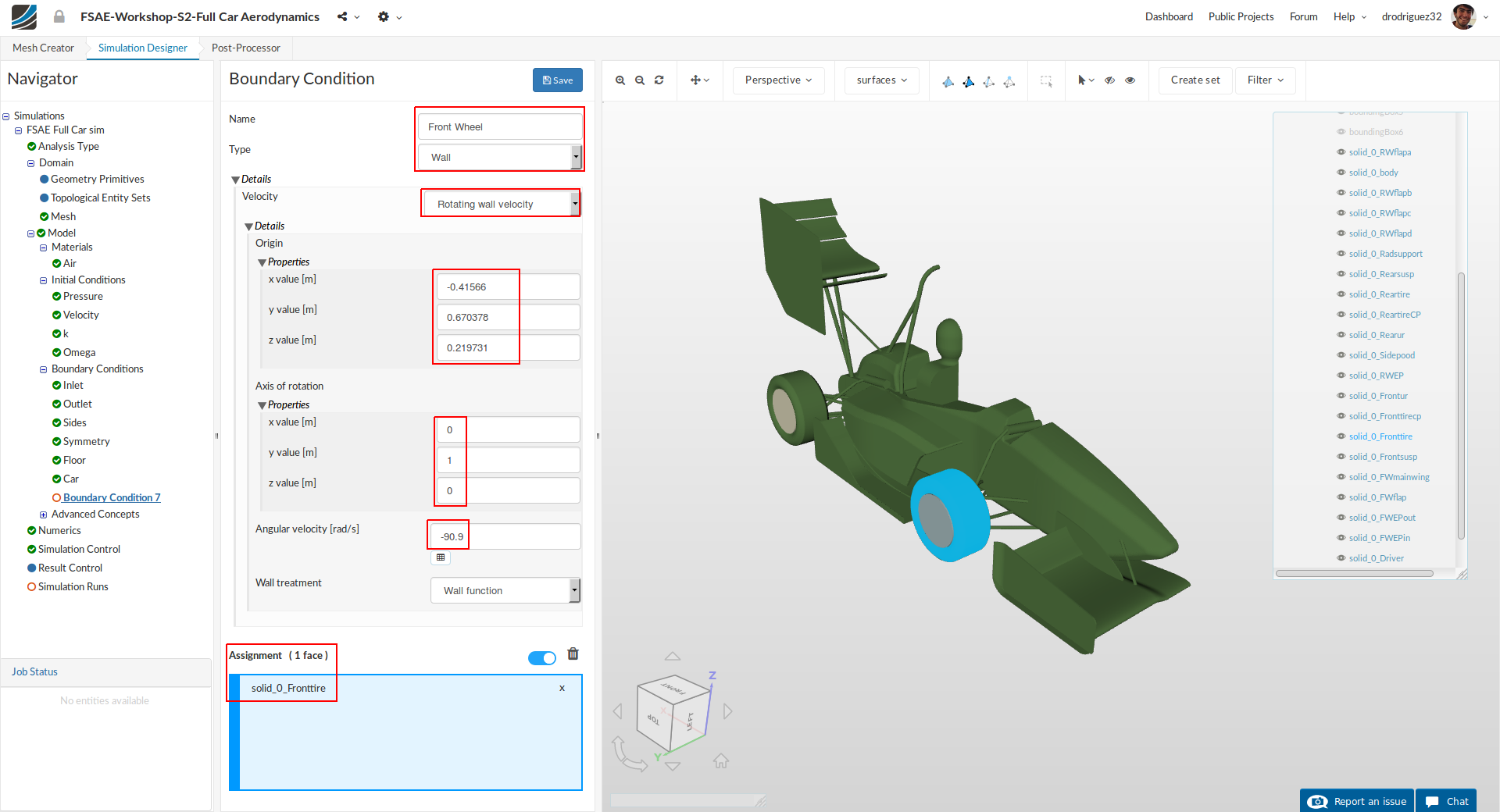
Create a new boundary condition and rename it to Front wheel (optional).
Change the Type to Wall and Velocity to Rotating wall velocity. Then change:
- Origin x value [m], y value [m] and z value [m] value to -0.41566, 0.670378 and 0.219731 respectively.
- Axis of rotation x value [m] and y value [m] to 0 and 1 respectively.
- Angular velocity [rad/s] to -90.9
- Then select solid_0_Fronttire.
- Click Save to register your changes.
Make sure your setup looks like the picture above.
Rotating wheel (Rear)
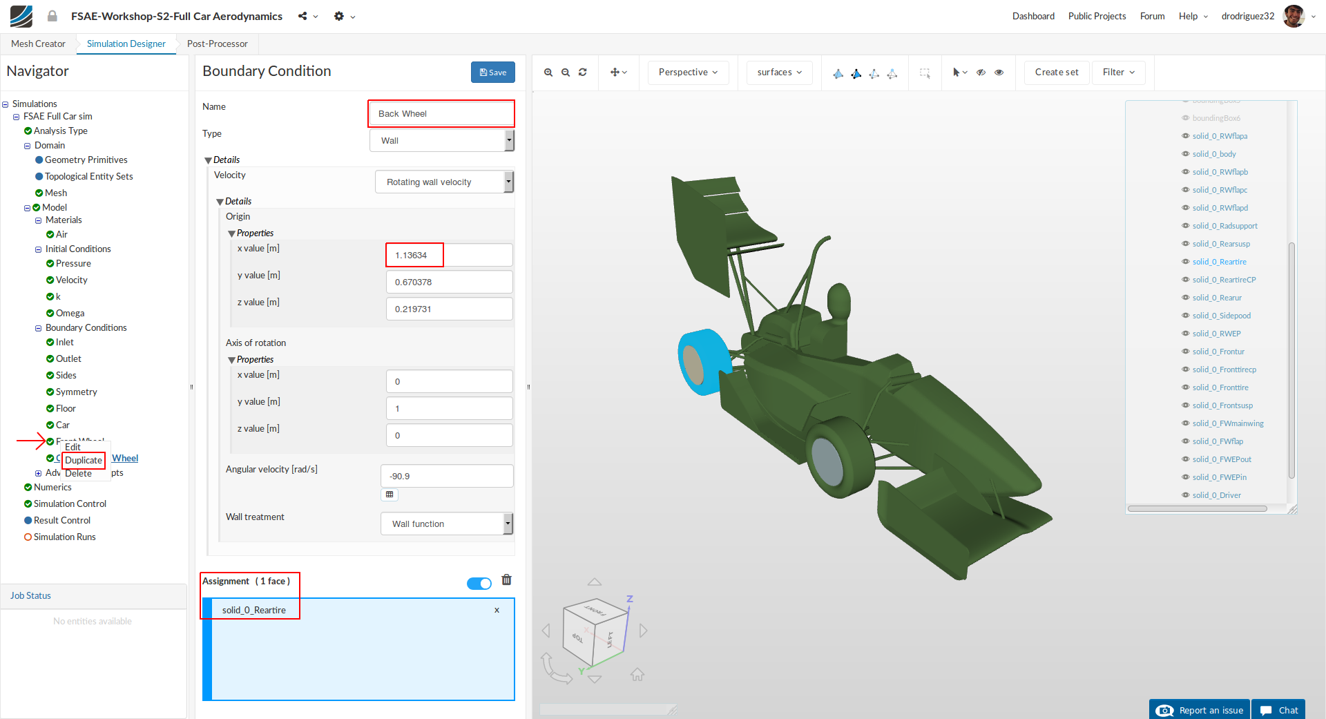
Duplicate the previous boundary condition by right clicking on it and selecting Duplicate. Rename it to Rear wheel (optional).
Change the Type to Wall and Velocity to Rotating wall velocity. Then change:
- Origin x value [m], y value [m] and z value [m] value to 1.13634, 0.670378 and 0.219731 respectively.
a. Notice that the origin values for the y axis and z axis are the same as the previous boundary condition. That’s why it was better to duplicate it. - Axis of rotation x value [m] and y value [m] to 0 and 1 respectively.
- Angular velocity [rad/s] to -90.9
- Then select solid_0_Reartire.
- Click Save to register your changes.
Recommendations About Comments
If you run into issues during your process, before adding a comment to the thread please consider the following:
- Go over the tutorial one last time and compare it to your setup. Is everything the same?
- Go over the existing comments. Maybe someone has had the same problem and it’s already solved.
- Is there an actual error? Or is it taking a long time to load?
a. If it seems to be a loading issue, please give it some time or refresh the page. Sometimes due to the internet connection the platform may seem slow.
If it’s a new issue that you can’t solve, please outline the issue as specifically as possible and include a link to your project. This will help us figure out what is going on faster and thus we can get back to you faster.
Link to part 2 of the tutorial:
Step-by-Step Tutorial Session 2 - Full Car Aerodynamics (Part 2)
