Mesh Operation failed two times on 18deg-5mm-up wing. Setup has been checked once again and it is same like this Tutorial. Any idea?
I had the same problem then I just changed the computing cores from 16 down to 8. Then it worked for me.
4 Likes
Thank you! It helped me and solve this issue.
2 Likes
14deg meshing finished successfully, but can’t select the 14deg mesh in domain. Ideas?
Hello Everyone,
Important Note:
If you are encountering Errors in Meshing of “Configuration-7: 18deg-5mm-up wing” geometry Please follow the steps below: (The reason for the mesh error is a small glitch in the decomposition of the domain for this case)
Step-1 : For this case, change the number of compute cores (from 16) to: 32 (or 8, but it will be slow) and rerun
If the above change does not result in a successful mesh then,
Step-2 : Change the number of cells for Background Mesh as shown in figure below and run with either 16 or 32 cores. (This helps to avoid the glitch in the decomposition process for this case)
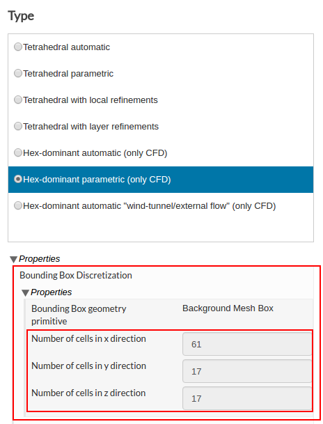
.
If the issue still persists, then please do let us know.
Thanks.
Best,
Ali
2 Likes
Hey @ChristianF! Seems like it worked for you. Do let us know if you have any other issue! 
Best,
Ahmed
As boundary conditions are very variable depending on the problem, wouldn’t it be more accurate to ask the solver to extract Pressure Coefficient (from static pressure field values) rather than using the Calculator filter? Cp values over 1.0 do not sound good for me…
Best,
Alex
Is there a way to do a “Plot over line”/“Plot on intersection curves” like filter, to extract surface data from a slice? (let’s say, get a surface slice from the main wing and flap and plot Cp vs X-coordinate).
If the solution is downloaded is an operation easy to do with Paraview or other post-processors. I was wondering if it’s possible to do it with the online-postprocessor of SimScale.
Thanks,
Alex
Hey Alex!
Thanks a lot for your query. This is quite a nice question and therefore need to be answered in detail.
You are absolutely right here, you can of course output the Pressure Coefficient solution field but the purpose here was to show the user how to calculate this value if they have forgot to output it initially.
This is because of the reason that according to the formula pressure at infinity is required which solely depends on the bounding box. the value of 6.2 which we are giving here depends on the inlet pressure value we are getting for the bounding box we have used. Since this bounding box is not big enough (in order to reduce mesh size), you can expect the Cp values larger than 1. If it would have been bigger, you should have got values either near or less than 1.
I hope this helps. If you have any further question/s, feel free to ask.
Best,
Ahmed
Yes you can do it but locally. After opening the results in Paraview you have to just apply the slice filter and then select a plot data filter over this slice filter which will plot the values over the whole slice.
Let me know if this doesn’t work for you.
Best,
Ahmed
Thanks for the quick reply Ahmed ![]() .
.
I agree that is didactic to show how to use the Calculator filter, but as on the Webinar there were some people that didn’t know what was the Pressure Coefficient, maybe showing wrong values of it could lead to confusion to aerodynamic students. Your explanation, however, explains a lot about how the distance from/to the boundary conditions may affect the solution, so in one way or the other more valuable information is being added to the workshop!
Best,
Alex
Thanks for answering. I had updated my question after you quote it, I’m afraid. I knew how to do it locally, I was just wondering if it was possible to do it on the online-postprocessor tool.
Cheers,
Alex
Absolutely right Alex! But due to time constraint some information may not be delivered properly in the workshop. But glad that you asked here so now everyone has an answer
Best,
Ahmed
Ah! I didn’t get that right! my bad!  Unfortunately for now its not possible. Each plotting feature of Paraview need some more improvements and modifications in online version. Therefore, needs sometime but we are looking forward to it.
Best,
Ahemd
Hello,
I would like to know how could I contact Rene Hilhorst for a student non-comercial licence of Optiprof, which is the software he used in this first webinar session. Thanks,
Carles
Hi @cbolart,
We will be sending out additional information about this soon via email, so keep an eye out.
Best,
Anna
1 Like
I am getting popup that the run may cross your qouta, so change your settings under simulation control , i had kept the same seetings as given above, what is the solution for this problem ?
Hey @Bhishma!
Seems like you are using a professional test account. Test account is made only for test purposes and has only 200 core hours. That’s why you are having a qouta problem.
Although it is recommended to initially create an online free community account for the homework purposes. But no worries, our support engineer will be here to help you with this. He will change your account to the free community and you are good to go. All you have to do is to just send an email to him at: srajendran@simscale.com (make subject of your email as computational qouta + your registered mail ID with SimScale in the message body)
For other users having this problem, please follow the same procedure.
After your account has been changed, you would be able to see 3000 core hours under your dashboard. This shows that the process was successful. But in order to further do modification in the same project, you have to make it public.
Hope this helps. If you have any question/s, feel free to ask.
Best,
Ahmed
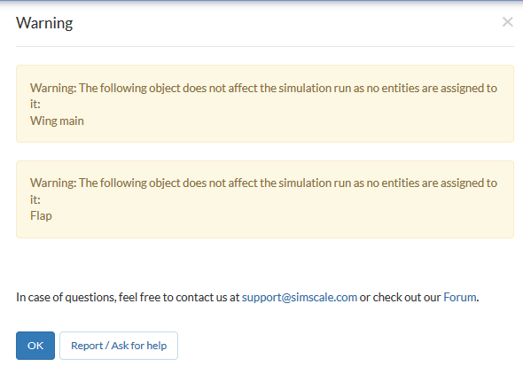
When I wanted to start second simulations this error was shown. I have selected faces of wing and flap in Boundary conditions. What could be wrong? There are all green checked symbols… Or shall I just tried to run this?