Simulation Run Error

Hey!! As part of an assessment task I was trying to run this simulation for an office room with an air conditioner(1.5 ton) with 12 people (symbolized as prisms) acting as heat sources of 70W each. I used hex-dominant parametric mesh operation, as it would allow me to refine the mesh locally for ex: close to the walls(which have a U value of 0.5). However, after setting the boudnary conditions, when I try to run the simulation named “Convective Heat Transfer Mesh 5” which has a multi region mesh and heat sources (defined as volumes) I keep getting the error- “The mesh contains more than one volume. This analysis type may yield unexpected results in this case. Proceed with care” and when I go ahead and try to run the simulation, 2 minutes into the simulation, I receive an error.

However when I don’t use a multi region mesh and don’t input the additional heat sources as in the case of “Convective Heat Transfer Mesh 4”, the simulation does run and eventually converges.

Please do have a look at the steps I’ve taken and Is there any way possible to tell me where I am going wrong or what am I missing?

LINK: SimScale

Thank you so much. Appreciate it.

Hi @ajohn1111mav,

The issue isn’t your mesh, it is the fact that you’ve assigned a wall condition to both your inlets and outlets for “convective heat transfer mesh 5”. Do refer to the pictures below. The first two are your inlet and outlet assignments, the last is your wall condition. Notice that you’ve overlapped the boundary conditions meaning that the flow is basically stuck. If you refer back to your successful simulation “convective heat transfer mesh 4”, you would notice that you didn’t make that mistake and it ran fine.

Also I would increase refinement particularly at the inlet and outlet as you want it to conform to the geometry as best as it can for such a sensitive area.

Cheers!

Regards,
Barry

2 Likes

Thank you so much Barry.

I will be refining the mesh around the air conditioner inlet and outlet furthermore.

I did remove the overlapping boundary condition, but I still am not bale to run the simulation. Two minutes into the run, the same error occurs again.

Two other doubts that you could help me clear are,

  1. While including heat sources, is it necessary to before hand have created a multi region mesh? or can the volumes be selected separately afterwards in the simulation manager?

  2. For convective heat transfer simulations is it not possible to determine the y+ values in the result control tab?

Thanks in advance.
Ankith

Hi Ankith,

So I’ve copied your project over, I suspect the issue has to do with your mesh rather than the parameters you set in this case. If you refer to the picture below, this shows up when you do a check.
1
If you perform the same check on your first successful run with mesh 4, it does not show up.

On how to remedy this, I have might have an idea but what did you change between mesh 4 and mesh 5?

Not the best to ask on CHT :stuck_out_tongue: But I’ll try my best. I doubt this is possible as you need to define the mesh regions first before you can simulate them. So I’ll say all of this has to be done in the mesher.

The result controls tab does have such a function but I don’t think it is available for CHT. I’m aware that incompressible simulations does have a y+ field calculation available.

Cheers.

Regards,
Barry

Hey Barry,

There are just 3 difference between mesh 4 and mesh 5,

  1. Mesh 5 has more number of cells in the x, y, z directions ~78
  2. The option to “create multi region mesh” is checked “true”
    3)“Mesh refinement 2” in Mesh 5 consists of all the faces in the domain except the walls and the air conditioner inlet and outlet.

Hi Ankith,

This shouldn’t be an issue. So no worries about that.

This setting might have issues, I suggest making a duplicate copy of mesh 4, just purely turning that setting on and attempting to simulate with it. Lets see if we can isolate the issue.

Sorry I don’t exactly understand this part. You mean you selected a surface refinement for everything except the walls and air conditioner inlet outlet? Looks like you select everything. For mesh 4 you selected everything?

Cheers.

Regards,
Barry

Hey Barry,

So as you suggested I created a duplicate “mesh 4” with that setting switched on and I still got the same error. So I guess that’s whats creating the problem?

PS: This is another account that I’m using as I crossed the core hour limit on the previous account.

The link to that same case now is : Mesh trial CFD Applications - Assessment Mesh trial by ajohn5mav | SimScale

Yes exactly. In mesh 5 “mesh refinement 2”, I had chosen a surface refinement for everything except the walls and air conditioner inlet & outlet.
While in mesh 4 “mesh refinement 2”, a surface refinement for all “faces” in the domain were applied.

But then again, this is not the issue, its the “create multi region mesh” option that’s creating the error.

So now how do you feel I should go about assigning heat sources to volumes? I did try to create a separate entity/zone for each source by selecting the faces but it does not allow me to assign the entity as a volume under the “heat sources.” tab.

Regards

Ankith

Hi @ajohn5mav,

I suspect so. Lets try refining the inlet a little. If you look at the mesh at your inlet, it is rather distorted. Try to increase the refinement levels to get a better mesh definition that you can assign your inlets and outlets to. You might also probably need to increase the refinement at the “inlet” area walls besides the actual inlet and outlet as well. Just make sure you check the mesh when you’re done. Do let me know how it goes.

Lets start with this first then we’ll work from there.

Cheers.

Regards,
Barry

Hey Barry,

So as you sujjested I did refine my mesh and emphasized the refinement at the inlet, outlet and all around the air conditioner as you can see in Mesh 4 from the link: SimScale

Fortunately, I figured out how to add heat sources to the human prisms in the domain by creating cell zones at the time of meshing and was able to run the simulation. (CHT 1 and CHT 2 are convective heat transfer runs, the only difference being the mass flow rates where that of CHT 2 is higher than CHT 1)

After post processing my results(see states CHT1.1, and CHT 1.2 and states CHT 2.1 and CHT 2.2, and screenshots CHT1.1, CHT1,2, CHT 2.1, CHT2.2), however, I do suspect from qualitatively analyzing the results that the values that I obtain seem slightly wrong as the flow of cooled air from the AC doesn’t seem to have any effect on the cooling of the room.

At this point I’m not really sure what is right and wrong as I tried multiple possibilities to the inlet and outlet boundary conditions in the hope of achieving satisfactory results. Maybe you could just have a look and analyze if I’m doing something wrong? and if so is it because of my boundary conditions or could it be my calculation of the mass flow rate?

While you’re in the post processing window, is there a bug in the software or something along the same line?, as I cannot create a second slice on the same domain. I was looking to create slices in the x and y directions, however the second slice would always end up being a straight thin line with hardly any width to it.

When it comes to the yplus value close to the walls, I did run the mesh along with a set of conditions as set in the Simulation - “Incompressible for Yplus” however, when I view my yplus range in the post processor, it just shows a value of zero.

A lot of errors and doubts, I do apologize, but I do hope you can help me out.

Thank you so much

Best regards,
Ankith

Hi @ajohn5mav,

Just saw your screenshots and it does seem like the simulation is not behaving as intended and the AC really doesn’t seem to have any effect like you observed. Convergence of your results also look very off and there seems to be significant error. Ideally you would want your convergence to reach 1e-4 to be considered as loosely converged but that also depends on your specific case which I’m unsure about.

While I continue to take look into your simulation regarding your post-processing woes, I suggest downloading ParaView and doing your post-processing there. Just quick warning that ParaView can seem to be quite daunting but it functions about the same as the SimScale post-processor. In ParaView you can perform a slice, select surface with edges and measure the layer size using the built in ruler function to then check your y+ value. On top of this, it will be much easier to manipulate your data. I’ll post some screenshots shortly to hopefully give some insight on what might be the issue.

No worries about the errors and doubts we are all learning here and problem solving is always fun. Except when there is deadline then welp. :stuck_out_tongue:

Cheers!

Regards,
Barry

Thank you so much Barry.
Well my specific case just has a 1.5 ton AC in a room with Human Prisms emitting 70 W each. The walls have a U value of 0.5 W/(m^2K) and the outside temperature is 303K. Nothing else is given. I need to analyze the performance of the air conditioner.

Yeah I am using ParaView now, really slow considering the size of the domain. That’s the only annoying bit.

Regards,

Ankith

Hi @ajohn5mav,

Yes Paraview is quite heavy on the computing resources. Get a computer with at least 16GB of RAM and it should load relatively quickly.

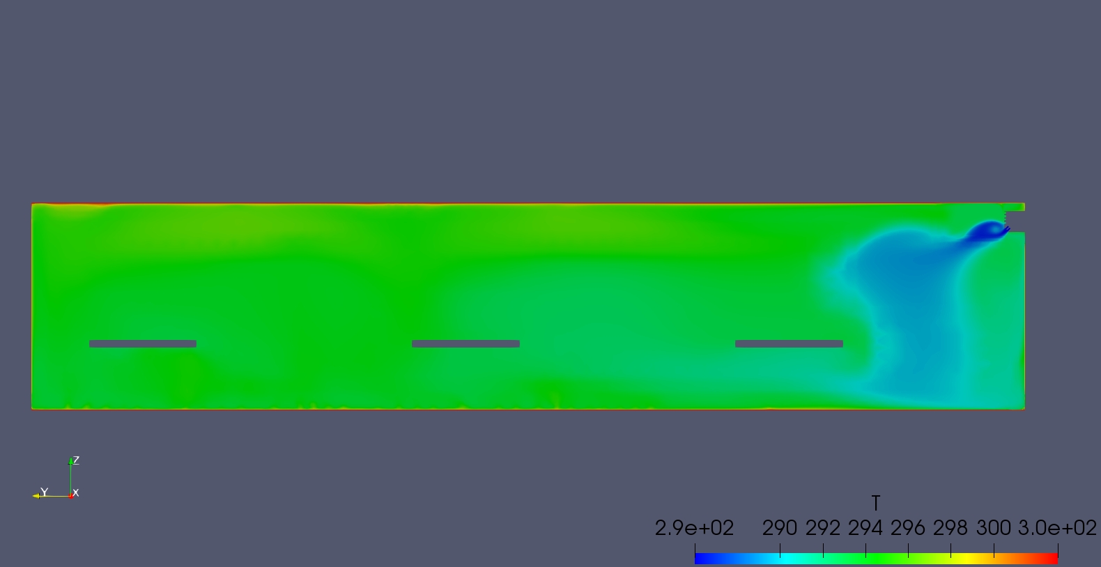
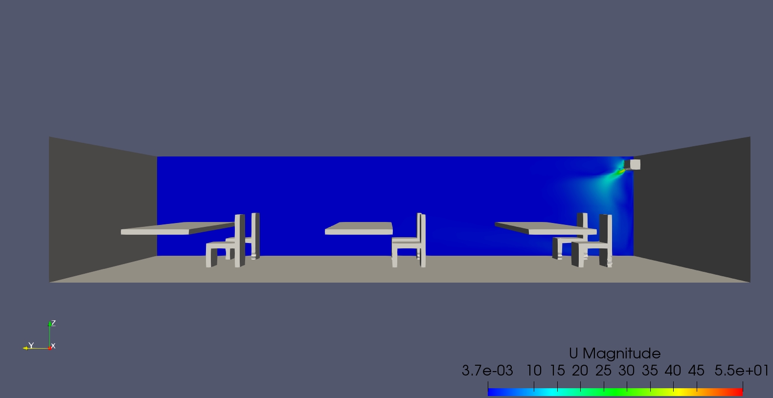
I’ve taken some screenshots do refer below. The first two are temperature slices and the last 3 are velocity slices with one of them being a streamline plot. These are all taken at the final timestep.

1. Temperature slice overall

2. Temperature slice near AC

3. Velocity slice overall

4. Velocity streamlines AC

5. Velocity slice AC

You would notice that your observation is indeed correct and the AC isn’t doing much to dissipate heat from the room due the flow just stagnating at the AC itself. There are several questions I’d like to ask.

Firstly, are your walls supposed to produce heat like that? If you refer to 1. the walls seem to generate heat as there is a temperature gradient. I guess this is alright if the building is not insulated? It just seems odd to me. Do let me know if this was the intended function.

Secondly the AC seems to be behaving as intended. However with my limited knowledge of ACs, I believe the room allows circulation because of small gaps around the room via doors or closed windows? On top of this, do the “outlet vents” kinda force air out as they have fans on them? These factors might promote circulation and make the simulation behave more realistically.

Thirdly, even with the things that promote circulation on the second point, I would assume that the movement of air due to the diffusion of heat throughout the domain will promote more circulation due to minor changes in the air density via temperature change. But in this case that is not happening. This could be two fold, something to do with the air settings or not enough iterations to allow the temperature change to propagate.

Lastly, is your AC supposed to be having such a “weak” inlet? It would seem that the AC is running at very low power or something so maybe you might want to check the flow rate or flow velocity of the AC.

I suggest considering the needed changes of the first two pointers I made first before re-running with a much longer timestep. Also I don’t think that you need to save that many data points, maybe 5-6 saves over the entire simulation time. It would help you to speed up downloading. Do let me know if you have issues with that.

Cheers.

Regards,
Barry

P.S Screenshots are all done in ParaView.

1 Like

Hi @ajohn5mav,

Just waned to share this link where SimScale goes over HVAC systems, hopefully it is of some use!

Cheers.

Regards,
Barry