Hi,
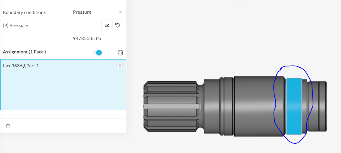
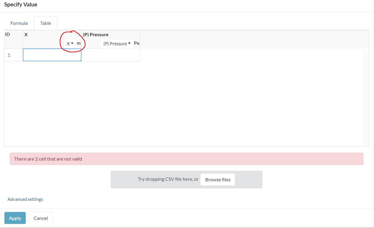
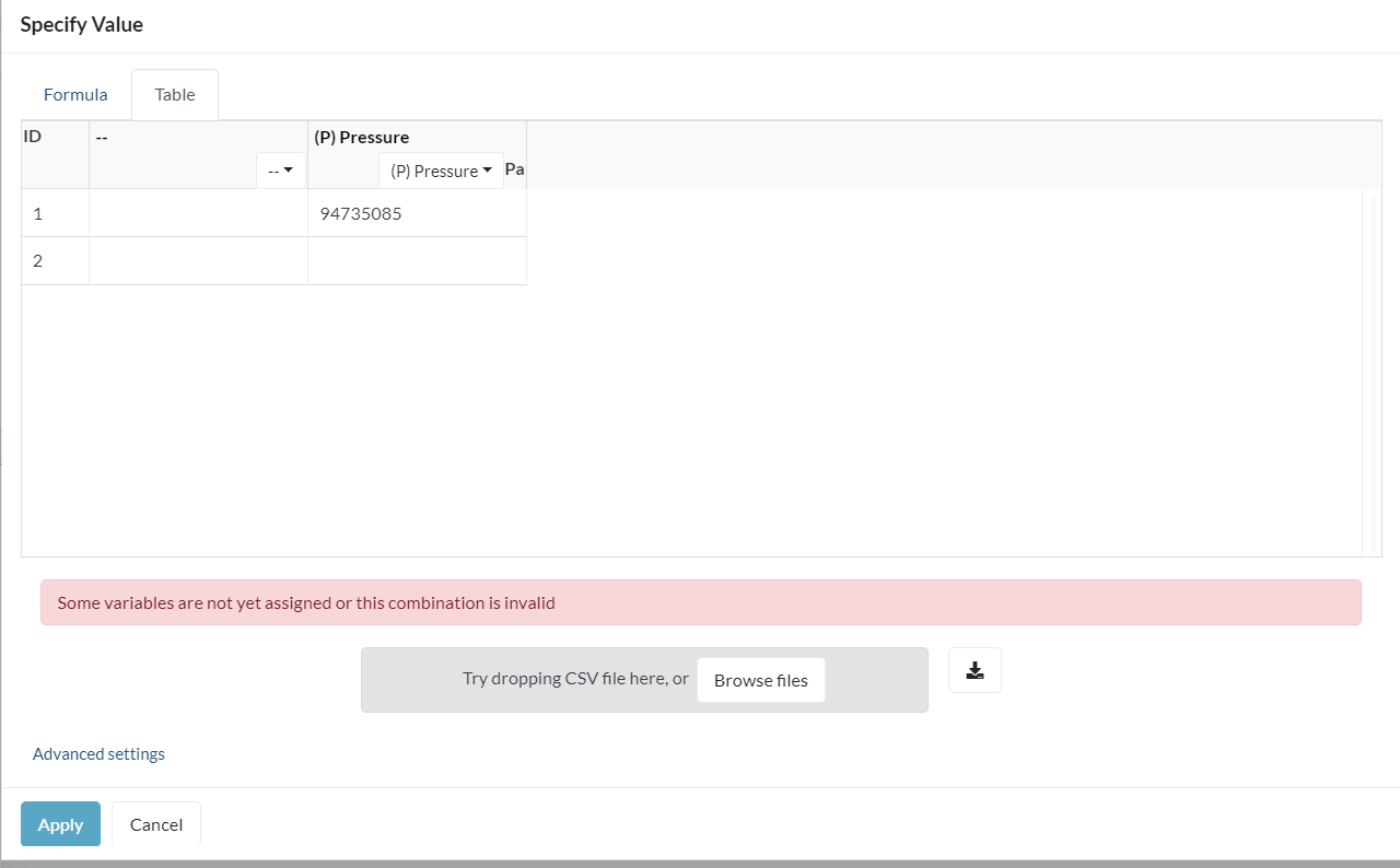
for the thermal analysis I have to do for a shaft (see picture below) I need to choose the relevant boundary conditions. However I can’t figure out what am I supposed to write in the second column (see picture), for instance, for pressure. The text says whether “There are two cells that are not valid” or “Some variables are not yet assigned or this combination is invalid” (see picture).
I’m guessing that I have to put in the dimensions of the area but shouldn’t SimScale already now that as I’ve selected it (Assuming of course that SimScale took over the right masses)
Hi @dzapryanova
I would like to add one point on which you should focus i.e a surface of your shaft should be assigned a fixed B.C in this simulation. I am more oriented towards CFD related problems so I am tagging Power Users to help you with this problem.
Thanks
Ani
1 Like
Hi @dzapryanova,
From what I see here, I think that you are a little confused about the boundary conditions. Here goes my explanation:
- If you are trying to apply a force in the X direction, the pressure boundary condition will not work, as what it does is to apply a distributed pressure normal to the surface you select.
- If what you want is to indeed apply a force in the X direction, use the Force boundary condition, where you will be prompted for the vector components.
- The table you are looking at is used to input a function, that is, for the case where the pressure is dependent on other variables. such as coordinates or time. The function is defined as a piece-wise linear curve, point to point.
Please comment if you have further doubts!
2 Likes
First of all, thank you for your quick response. Now, I get what you mean but I’ll try to explain my reasoning for using the Pressure BC and not the Fixed Force one. This is a input shaft to a planetary gearing and a planetary carrier is pressed to this particular area, which essentially would mean I have forces in Y and Z directions. I used a formula to calculate the overall pressure and I don’t think is dependable on any other variables. So I probably shouldn’t fill in the table , should I?
It wouldn’t worry me that much if the text didn’t pop up in red, which lead me to believe this is why the simulation failed. (Because it did fail  )
)
Thank you again!
Hey @dzapryanova!
I would say that a BC is missing, namely the one “holding” the shaft mentioned by Ani in post #2. However I would not get with a fixed BC but rather an elastic support which would allow rotation, and model the torsional rigidity of the shaft portion.
For the pressure if known you can either fill out the vector components of the force or indeed work with a pressure boundary condition but use a coordinate like X,Y or Z to define some sort of parabolic pressure distribution along the face. Do you know how the pressure is (approximately) distributed?
Best,
Jousef
Sadly no. But w e have to make a function for the pressure distribution along the whole shaft, don’t we? As far this area goes, as the other part is pressed completely to the shaft, I would say its constant, or?
Also, for these coordinates: do I make up the numbers myself? Because I assume that the coordinate system is positioned right at the beginning of the shaft, however not sure where exactly.
Thanks again!
I would not say the whole shaft but only the portion where the planetary carrier is located as depicted by you in the first post (the blue face). The pressure is constant if we assume non-elastic bodies (which you can indeed do in the first step - start easy and then successively increase complexity). For elastic bodies you have a somewhat “parabolic” pressure depending on the angle \alpha of your shaft (see Hertzian theory for more information on that but only if you are interested, that’s not part of the exercise).
The boundary condition you want to go with in your case is this one: Surface Load | Boundary Conditions | SimScale - rather trivial but did not think of that in the first place, kudos to my colleague @rszoeke for the hint.
Cheers,
Jousef
1 Like
Hi,
In that case, you can use the formula tab instead of the table input, because you have an analytical expression for the pressure. In there, you can enter your formula directly. By the way, if you share your formula and model with us, we should be able to help you even more.
About the temperature distribution, as this is a steady state solution, if both faces have the same temperature then you will not see any gradient, just the whole model will converge to a uniform temperature field. Try applying different temperatures on different faces to check if you get a gradient.
2 Likes
Hi, just one additional comment.
@ggiraldo is totally right, as its steady-state and you only have one fixed temperature BC given the whole body will eventuyll reach that exact same temperature.
I think there is a misunderstanding in the meaning for this temperature as it has different meaning for different places where it is mentioned. I think you refer to the reference temperature given in the material properties. This actually defines the temperature at which you would consider zero thermal strain, and not the ambient temperature.
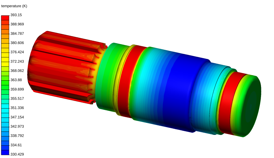
If you want to have an ambient temperature influencing the simulation, you should add a convective heat flux boundary condition with the ambient temperature as reference temperature and an appropriate heat transfer coefficient.
Result would look similar to this:
Best,
Richard
4 Likes
Just to be clear we are talking about the pressure from the planetary carrier, right?
This here is the formula
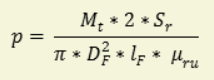
and I have all the parameters (all of which constant ), which is why I substituted everything and didn’t use any formulas. From what I’ve read on the site about formulas X,Y,Z are the displacements in each direction and I don’t think I have any in my case.
Is this what you meant?
Best wishes,
Demira
Can you please list what each parameter is? Also, where does this pressure acts on?
I do not see any coordinate, and if everything is constant, why do you want to use a formula?
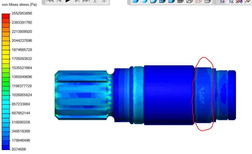
If you scroll back to the top (the first picture), there’s a blue face portion of the shaft, which I’ve circled. This is where a planetary carrier is pressed and this formula calculates the minimum pressure needed for the planetary carrier to stay in position. It not like I want to use the formula , I’m just trying to figure out why this portion doesn’t seem stressed at all in the end results of the simulation (see picture, circled in red)
Btw as recomended I used a surface load BC in this part of the shaft
Hi @dzapryanova!
It’s not that it is not stressed but more the scaling of your stress as the regions with red experience a higher stress than those you marked in the picture (do a hand calculation and see if the simulated stress is approximately the one you calculated). You can use re-scaling to see which region is above a certain threshold to make some conclusions out of it. For instance if you choose the yield strength for re-scaling you can see which part of the component fails or calculate the factor of safety (yield stress/v. Mises).
Cheers,
Jousef