Setting Up a Simulation Using Porous Media

Greetings, everybody!

I’m having problems trying to simulate a flow passing inside a pipe through a porous element. My purpose is to simulate the airflow through a radiator and compare the pressure drop obtained with the manufacturer’s data I have available. The problem is I don’t know how to set the parameters properly. I’ll show you all the steps I’m taking in order to get this simulation running. You can also access the project: https://www.simscale.com/workbench?publiclink=4738ed9f-c2d1-4290-8e71-6f0fc72992f4 (Check Simulation 2)

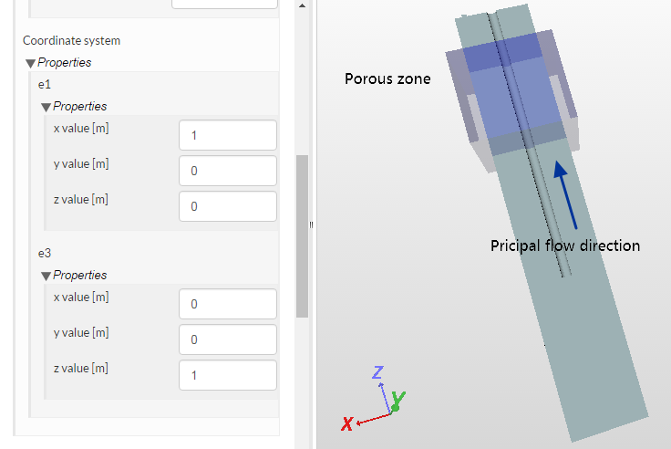
The analysis type is Compressible Steady State Flow Simulation, Turbulence Model: Omega SST. The radiator I want to simulate is represented by the Cartesian Box in the picture bellow. The Porous Media characteristics will be applied in this same Box.

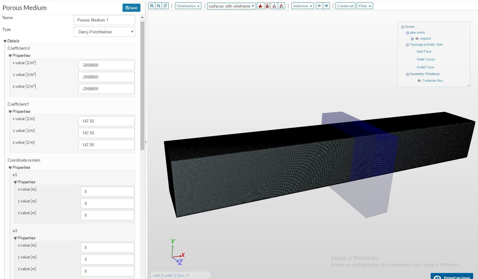
The Darcy-Forchheimer coefficients were determined following the instructions I found in this LINK, which contains some FLUENT instructions. The specific method I’m referring to is found in the topic “Deriving the Porous Coefficients Based on Experimental Pressure and Velocity Data”. Since I have the manufacturer’s Pressure Drop Data, it was possible to determine the Pressure Drop per Flow Speed in the core of the radiator and follow the instructions on that link.

With the coefficients ‘d’ and ‘f’ determined, I now need to fill in the Porous Medium parameters on SimScale. As you can see in the picture, the flow will move in the X direction. This is why I want to set the Porous Media in a way that its permeability is ONLY in this direction. I don’t want the Porous Media to be ISOTROPIC. It has to work only in the X direction.

With that being said, I need help filling these parameters. What changes in the simulation if I only set one of the 3 values (x,y and z) in each Coefficient (“d” and “f”)? And how should I set the vectors e1 and e3?

Finally, if I wanted to simulate a ISOTROPIC porous media, how should these same parameters be filled?

Thanks!

2 Likes

@ibrito, welcome and thanks for posting your question in the forum!

I know @varsey has worked on a simulation of this nature in the past. Let’s see if he has any comments on this one.

1 Like

HI @ibrito!

This is a good question, since I haven’t seen anywhere clear description of porous media setup in OpenFOAM.

Quickly answering your questions based on my modest experience:

First of all, if you want to create non-isotropic porous media, you should put the value of ‘f’ and ‘d’ coeffs only in those directions you interested in. So if you media flows in X direction, put values only in ‘x value’ field. Zeroes in other fields will mean that in Darcy-Forchheimer equation drag is being created only on x direction:

The second thing: e1, e2 are the principal directions, so your porous media will be aligned along this directions. For example, if you have a porous zone inclined of 45° with respect to the x direction of the reference frame in your mesh, you should replace e1 with something like (in 2D)

e1 (0.70710678 0.70710678 0)

If you keep

e2 (0 0 1)

the second direction is parallel to the z axis.

For example, in my case I set up e1 and e2 vectors the way you can see at the pic:

And you can look at this project as a reference as well: link

And the last thing I should mention is the exact values of ‘d’ and ‘f’ coefficients calculation. Unfortunately, I didn’t calculate them for my case myself, but used help of colleague of mine. I’m not sure how he did it, but I know that he used reference book with experimental values of porosity for our media and dimensions of ‘d’ and ‘f’ coeffs , after he gave me numbers we made a simple simulation in tube to prove those numbers work fine. I’ll try to reach my colleague and find out more details.

Hope this will give you right direction to move!

5 Likes

Excellent tips on this topic @varsey!

2 Likes

Hi everyone! Thank you for the attention, especially you @varsey!

However I still couldn’t get this simulation running. You explained the e1 and e3 vectors but I didn’t quite understand the diference between these vectors and the Darcy-Forchheimer’s.

In my example I should set my Darcy-Forchheimer parameters’ vectors in a way that the ‘Y’ and ‘Z’ components are zero, right? It means that the porous media is only permissible in that direction (X). With that being said, what does these e1 and e3 vectors really represent? Once I determined the direction of the porous surface, what will theses e1 and e3 vectors change? I’m sorry but I couldn’t understand the physics behind it. That’s probably why I still can’t run this simulation without resulting in errors.

Thanks in advance for the attention!

Hi @ibrito!

I quickly looked at your case and it seems like the problem you have is not connected with porous region. The problem is in the BC set up - the better options for your case, i believe, is to choose “wall function” and “zeroGradient” at the walls boundaries. This way setup should be more stable.

Also I think your mesh is not optimal (through it’s not crucial problem, i guess) - you can make it a little corser but with the boundary layer in it. This way it will be faster to calculate and more robust for numerical scheme. To look up how to do this kind of mesh you can check out almost any public project of flow in pipe simulatiom, for example in this tutorial.

When you get a good result without porous media, you can easily add it to see if it brings new problems or not.

Sorry I can’t change your project to help - I ran out of my quota, so I hope my advice here will be helpfull enough.

1 Like

@varsey - we’ll add some more core hours to your account, thanks for your efforts :slight_smile:

1 Like

Thank you @AnnaFless, I really appriciate it! :slight_smile:

1 Like

@ibrito, hello!

I set up your simulation the way you can see in this project. As you can see, I’ve created a coarse mesh with boundary layer + changed boundary conditions at walls and it works pretty wel now.

A couple of things I’d like to mention regarding you project - first of all you have a pretty fast flowing air,so you should choose “turbulent” simulation (as you did in simulation 2 and simulation 3), not a laminar (as you did in simulation 1). Usually before CFD simulation you calculate Reynolds number for your case to be sure if you choose laminar or turbulent simulation set up.

The second thing is that if you simulate isothermal flow (without temperature change within the domain) you can put “zeroGradinet” BC for temperautre at the wall. It means they are not able to transfer heat and this is the most robust set up in this case.

The third one is that you should’t use negative constants in porous media set up as you alredy have “minus” sign in D-F equation (see my first post in this thread).

Sorry to be probably too much into details, but I just wanted to share points I noticed during your case configuration.

Have a great time using Simscale!

2 Likes

Hi everyone,

Just to finish what we discussed here: the specific example how to find out what numbers exactly you put in a porous media properties is the following: the darcy eq. in OpenFOAM (eq. 3 here) you put in correspondance with semi-emperical data here - slide 207 here - eq (6.4-14).

This gives you the following equations:

  • d = 150 (1-eps)^2 / (eps^2 * D^2)

  • f = 2 * 1.75 * (1-eps) / (eps^3 * D)

Where eps and D is characteristics of your porous media (porosity and mean particles diameter).

4 Likes

Hi @varsey!

First of all I’m sorry for the absence, and thank you for your review on my simulation. I really appreciated!
Regarding your last post, about the specific example on how to find the D-F numbers, I took a look and it seems really interesting. However I don’t have some of the important data about the porous zone geometry I’m trying to imitate in these simulations. For instance, I don’t have the mean particles diameter (D) nor the porosity (eps). All the data I have is the pressure drop per mass flow and the basic dimensions of the radiator, like frontal area, length, depth and height. With these I can estimate the flow velocity in the core of the radiator and plot a Pressure Drop x Flow Velocity graph.

Checking these equations I noticed that there are similar equations in that material I first referenced to, in this ANSYS TUTORIAL LINK.

If you check equations 7.19-17 and 7.19-18 you will see the similarity. Like I said before, the problem is I don’t have those parameters (D and eps), however the therms alpha and C2 I managed to find in the way specified in that same web page in equations 7.19-23 to 7.19-27, with the Pressure Drop and Flow Velocity data.

That method gave me a negative Darcy parameter, which I though it was OK because in the example this same coefficient is also negative. Now I’m not sure if it is correct.

Thank you for your attention @varsey, I’ll keep trying. Once I get it right I’ll share here the procedures I took.

Regards.

1 Like

@varsey,

great resources - especially the slide deck / book. I didn’t know that on slideshare they have entire books! Will test this as well. I think such computations should be built into SimScale. What would be from your perspective a more convenient workflow to define porous media within SimScale?

Best,

David

1 Like

@dheiny

To be honest, I dont see anything to improve here at the moment, since what we are having now in the means of porous media configuration in Simscale are the native OpenFOAM tools with it’s pros and cons.

I’ll let you know if figure out the way to improve this aspect.

@ibrito
Hi.
I have a problem at hand for which I think I need to simulate as flow through porous media.
Could you please tell me how did you start-off with this simulation (the one you have posted)?

Did you upload a mesh?

Thanks in advance.

Thank you for the calculation formulas for the Darcy/Forchheimer coefficients.

I am just wondering about the eps^2 term in the calculation of the Darcy coefficient. Shouldn’t this not be eps^3 taking into account the Ergun equation and the ANSYS TUTORIAL LINK by ibrito?

2 Likes

Hi @pwoll !

Yeah, you absolutely right, I guess it’s a mistype because in all the references provided within this thread the power in equation is equal to 3.

Thanks for carefull reading!

Hi there!
This is a really useful post about the Porous media settings.
About the Darcy-Forchheimer formula I have found another mistype about the f coefficient:

f = 2 * (7/8) * (1-eps) / (eps^3 * D) = (7/4) * (1-eps) / (eps^3 * D) = 1.75 * (1-eps) / (eps^3 * D)

(So, it is not “2*1.75”, but just 1.75")

So the final formula seems to be the following:

DP/L = d * mi * U + f * rho * (U^2)

DP/L = (150* (1-eps)^2 / (eps^3 * D^2) ) * mi * U + (1.75 * (1-eps) / (eps^3 * D)) * rho * (U^2)

You can find this on page 191 of the here 50 - eq (6.4-12).

Cheers
Vincenzo

4 Likes

Hi Vincenzo,

Thanks for the correction and the corresponding source! Information like this is always invaluable.

Cheers.

Regards,
Barry

2 Likes

@varsey
do you know how to calculate forces and forces coefficients on porous body ??

1 Like

Hi @zeinelserfy!
If you mean Darcy’s law coefficients, then last time I needed to simulate porous media I followed instructions from here - How do I Calculate the Porous Media Parameters - YouTube