But we have to change values for k, omega and the dynamic viscosity like it is mentioned in the webinar by Milad…
Hello @hfoester,
The values defined under Initial condition is considered only during start of the simulation. As the computation progresses the solver computes and updates each of these, k, omega and dynamic viscosity, depending on the velocities for the complete domain. The end result would be the same after attaining steady state. You can choose the values which ever you prefer 
Regards,
Sam
Thank you very much. I wasn’t sure if it would make a difference in the final results when you use variant initial conditions
 Great tutorial!
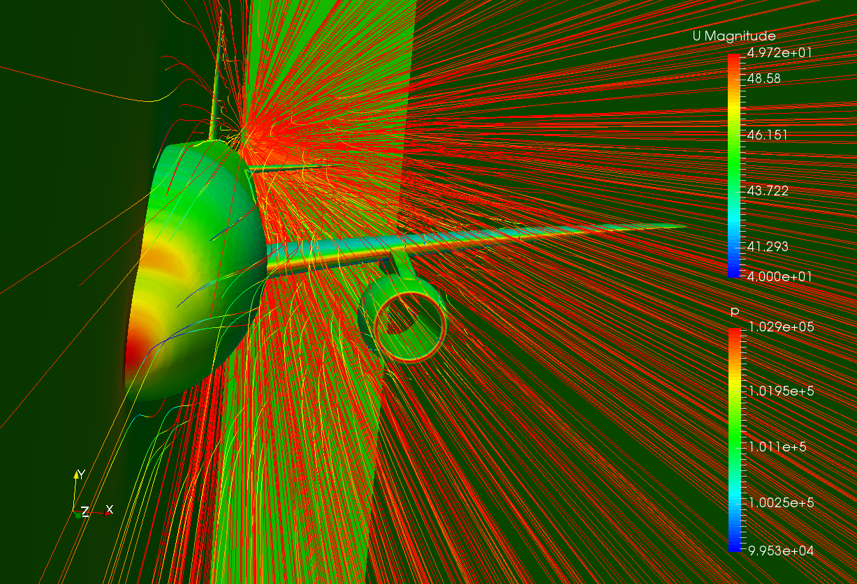
This is pretty cool, I didn’t know SIMSCALE had this ability. Perhaps soon enough we will be able preload results into simulations to aid in convergence and stuff like that. Good work!
I think the main difference is how long it takes for convergence to take place and sometimes stability of the calculations.
Hi, one question out of the actual homework:
Is there the possibility to get information about drag/ lift forces and moments in this simulation like it was done in the Formula1 workshop by using result control items? I don’t find this function in this homework, maybe it is because we are simulating with compressible fluid conditions?
2 Likes
Hi @sjesu_rajendra first of all to congratulate about this terriffic workshop I’m amazed about all the things we can do with Simscale!.
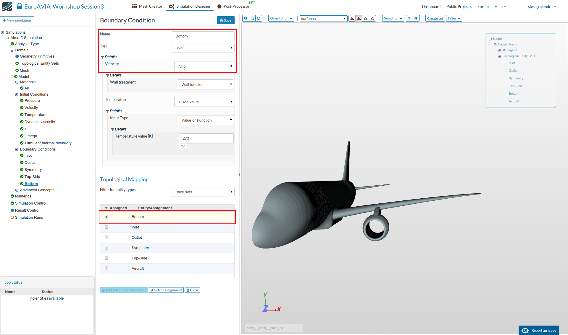
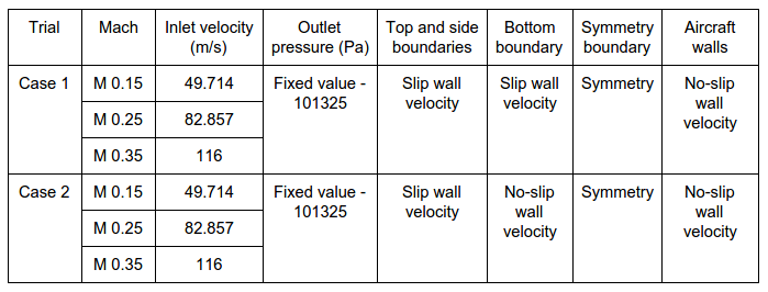
I have one question, about the “aircraft close to ground”, should we change in Boundary condition “Bottom” the Velocity type to No-Slip and Temperature Set gradient to zero?
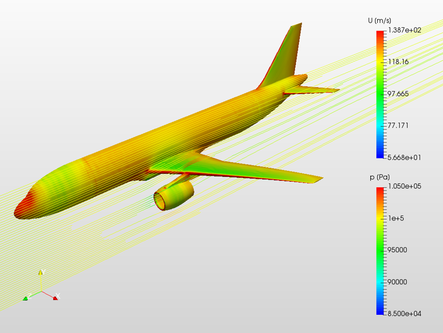
Picture from Top-Side and Bottom Walls :
Hi @hfoester
We will be adding the force and moment calculation for compressible flow to the platform soon. It will then be under Result Control items similar to in-compressible case.
Best,
Ali
1 Like
Hello @mlarreta,
Thank you for the feedback ![]() There are many other types of simulations, with varied applications, that can be done using SimScale! We will try to put them in the forthcoming webinars and workshops, and also as discussions through the forum
There are many other types of simulations, with varied applications, that can be done using SimScale! We will try to put them in the forthcoming webinars and workshops, and also as discussions through the forum ![]()
To answer your question, Yes the boundary condition of ‘bottom’ needs to be changed as per the table data in the previous post of this session. The temperature can be maintained to be at a fixed value.
Regards,
Sam
1 Like
Hi @sjesu_rajendra my simulation gives me an error message for all 3 runs in Case 2 (aircraft close to ground). According to the solver log, it states that the maximum number of iterations are reached.
I have tried changing the bottom boundary condition from slip to no-slip as stated above as well as changing the temperature to “set gradient to zero” but it still gives the same error message. I would greatly appreciate your assistance.
Here is my project link: https://www.simscale.com/workbench?publiclink=d4fab48a-d0c0-42fb-89da-af823f1345da
Thanks for your help!
Hello @Lt2Adnan,
I had a look to your project and see that the mesh setting requires a change. I believe you have changed the number of cells in z-direction to 57, whereas it is actually the cells in y-direction that needs to be reduced. We do this in order to make sure that the aspect ratio of cells in the domain is as close to 1 as possible.
Regards,
Sam
Hi @sjesu_rajendra, I have the same issue @Lt2Adnan has, and I do have the reduced cells number in the y-direction, at the first shoot I realize that I didn’t update the Maximum run time to 30000, but the second shoot ended still with the error an less free hrs ![]() Project:
Project:
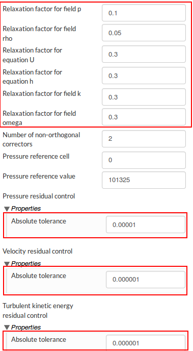
Thanks for reporting the issue. Stricter conditions might be required with regard to the numerics. Please try running the simulations with the following settings only for Case 2, and it should work. Other properties than the ones discussed below can be maintained to be the same as Case 1.
Relaxation factors:
- p - 0.1
- rho - 0.05
- U - 0.3
- h - 0.3
- k - 0.3
- omega - 0.3
Residual control - absolute tolerances:
Pressure - 1e-5
Velocity, Turb. kinetic energy and Omega - 1e-6
__
Solver settings:
- Change relative tolerances of all the solvers to 0.005
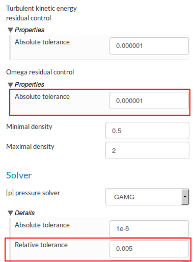
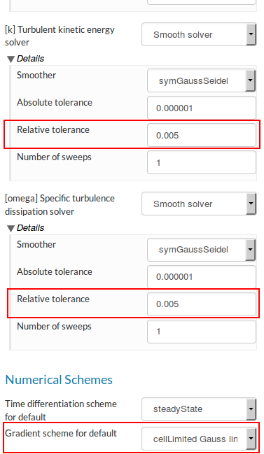
Numerical schemes:
Gradient scheme for default - cellLimited Gauss linear
Regards,
Sam
1 Like
 Amazing Tutorial.
But can anybody tell me:
- In post-processing how can you get exact similar view and zoom as compared to another case (except the three principal axis)
- Is it possible to rotate the geometry in-plane. By in-plane I mean that we do not change the viewing plane but instead rotate it. For example Making X axis vertical from horizontal position and Making Y axis horizontal from horizontal position
- Is it possible to use post-processing performing on a result onto another result file.
Thanks!
Regards
Abhishek
I have also the same problem with: Maximum number of iterations exceeded.
But only for Simulation M0.15 and M0.25 of Case 1.
All other simulations finished without errors.
So I am not sure where I did something wrong. My Project link: https://www.simscale.com/workbench?publiclink=8961874f-15bf-4490-85d4-4327025207e9
Kind regards
Hello @hl68fx
I saw your case and I found 2 differences than the tutotial:
-
For Wall boundary condition of Aircraft, you need to use No-Slip condition for velocity and not “Zero Gradient”. While Zero Gradient condition is to be used with Temperature and not “a fixed value”. This is most likely cause of failure of your simulation as you are trying to simulate the aircraft with Neumann BCs.
-
Either in Bottom wall or Top wall, I guess you have used T= 293K. I am not sure. But anyways it just for your correction. I do not think it will pose any error though.
I have tried your simulation and they are running good now. THe link to the project is:
https://www.simscale.com/workbench?publiclink=63ebb64c-aa22-4c70-a775-8a0964d2b988.
I hope this helps. All the very best.
Kind Regards
Abhishek VERMA
1 Like
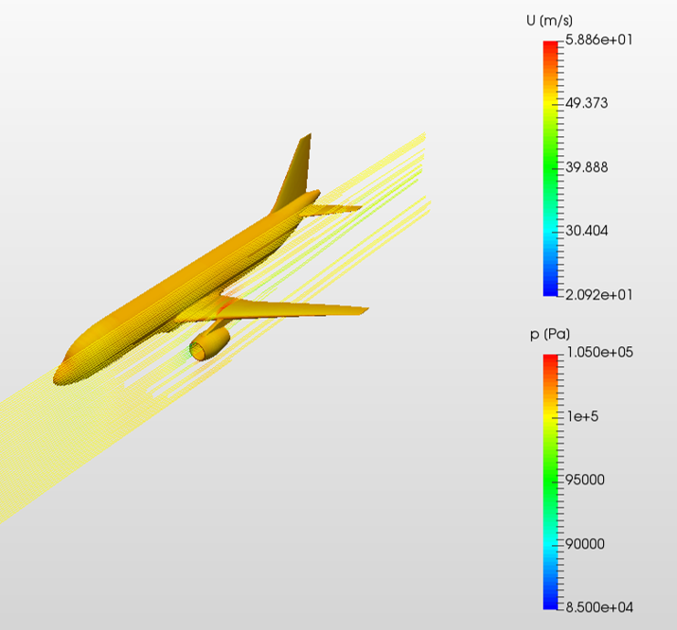
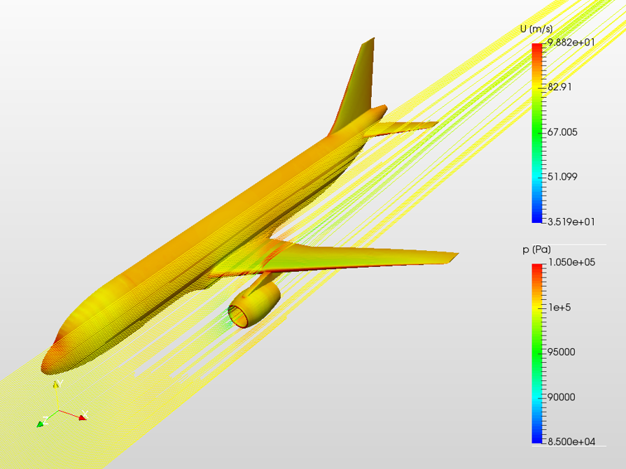
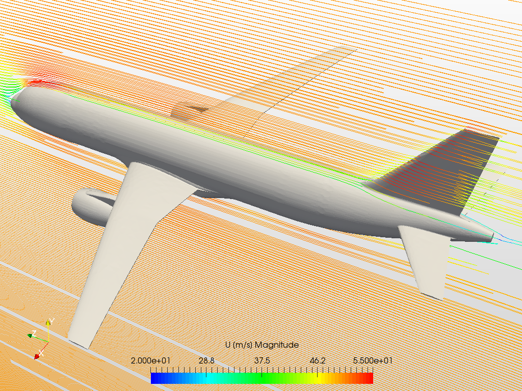
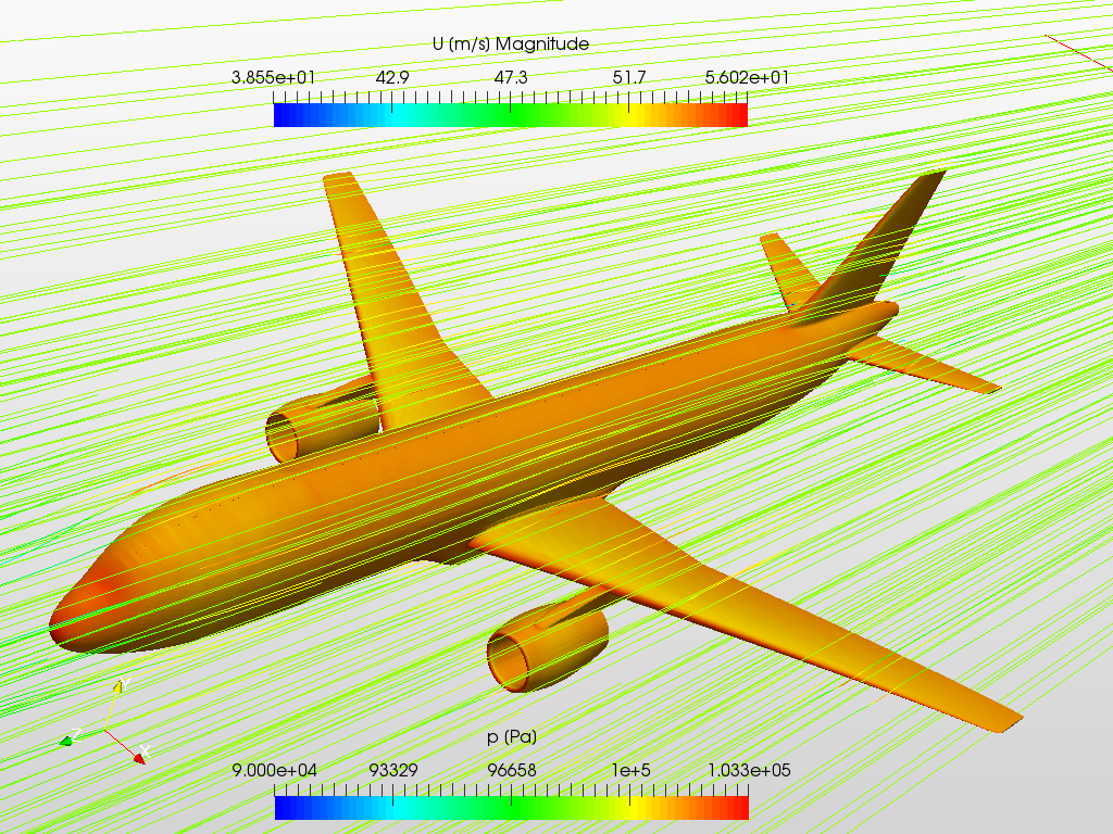
Thanks @sjesu_rajendra it worked excellent!, I’m currently playing with the filters, preparing it for homework delivery:
Very nice tutorial and workshop I really enjoyed it. 
2 Likes
-
If you dont care for a certain angle, only that it is the same in each case, right click on solution fields, add result to view, and adjust your visible layers.
-
You might try with the “Transform” Filter.
If you rotate by 270° around the z-Axis, x points up and y points in the plane of the wing. Is that what you mean?
If you want a view from a certain point, you could use this filter to align the data (and set your viewpoint by clicking under viewport tools get the camera in a “Zero-Position”. -
If you mean something like “Safe this filters and use them on this other result”, yes, this would be very useful. Tell me if you find out how to do that