Aerospace Workshop Session-3 Homework
Recording

Homework submission
Submitting all three homework assignments will qualify you for a free Professional Training (value of 500€) as well as a certificate of participation.
Homework 3 - Deadline Date 07.08 at 12:00pm
Exercise
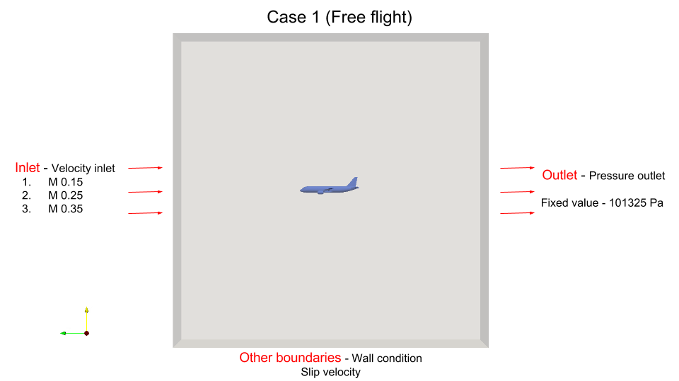
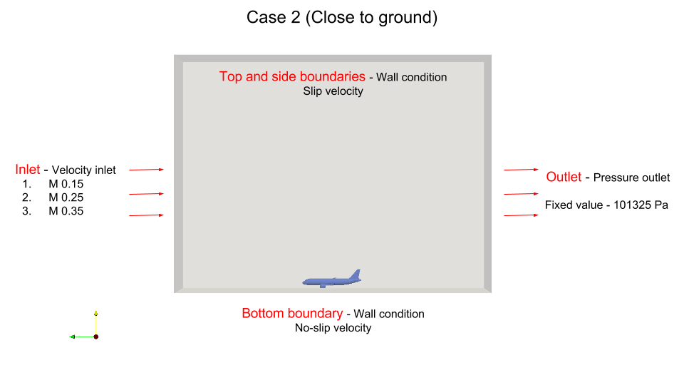
The task is to perform the aerodynamics simulation of an Aircraft model at different flow velocities and 2 different setups. First case is with free domain boundaries and the second is close to the ground.
The figure below describes briefly the two cases:
__
The table below gives the flow velocities for the different setups :
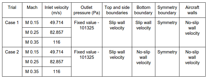
Note: For cases with M=0.35, Velocity Ramping is required via a file upload which is explained later in the simulation setup.
For these cases we will use the “Hex-Dominant Parametric” meshing operation which provides full functionality to mesh complex geometries. The Tutorial below will provide detailed steps on how to use each meshing feature to get a well resolved mesh.
Step-by-Step
Import the project by clicking the link below. ( Crtl + Click to open in a new tab )
Click to Import the Homework Project
Once the project is imported, the workbench is automatically opened. Then follow the steps below for setting up an incompressible flow simulation.
Mesh-1 (Free domain boundaries)
Geometry
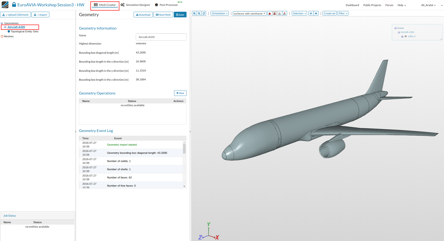
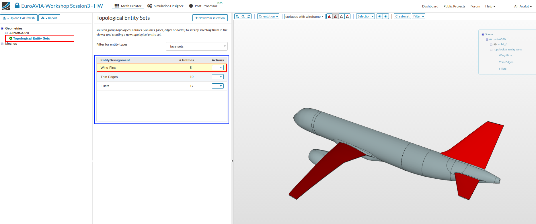
Note: The imported geometry has pre-created ‘Topological sets’ for some essential geometry faces. These sets will be later used for mesh refinements.
The created Sets are shown in the figure below, you can click to highlight the set in red.
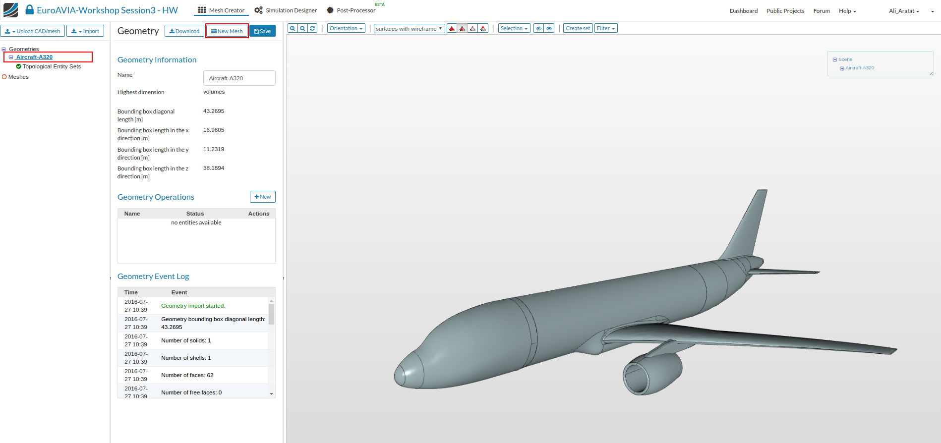
Creating a Mesh
- Select the geometry and click on ‘New Mesh’ button to create a new mesh operation as shown.
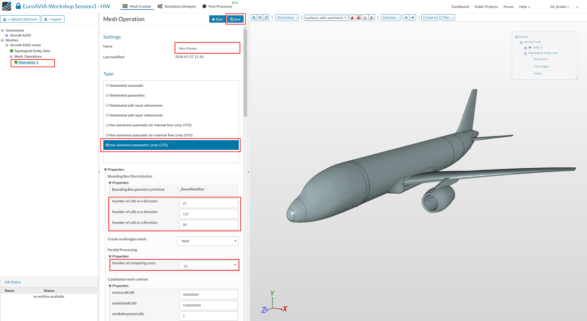
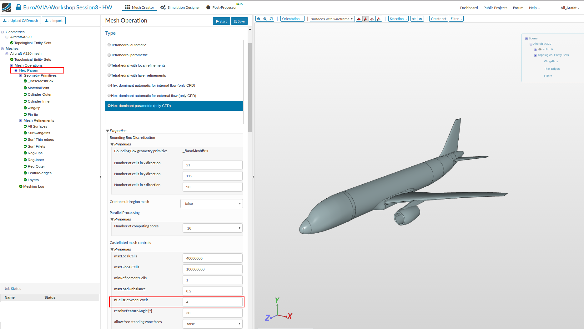
Main Settings
- In the Main Settings , select “Hex-Dominant Parametric (CFD)” . Then specify the following parameters and click Save.
Number of cells in X-direction: 21
Number of cells in Y-direction: 112
Number of cells in Z-direction: 90
Number of computing processors: 16
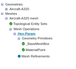
- After saving the tree is extend with 2 new entries, called ‘BaseMeshBox’ and ‘Material Point’ which must be defined.
Geometry Primitives
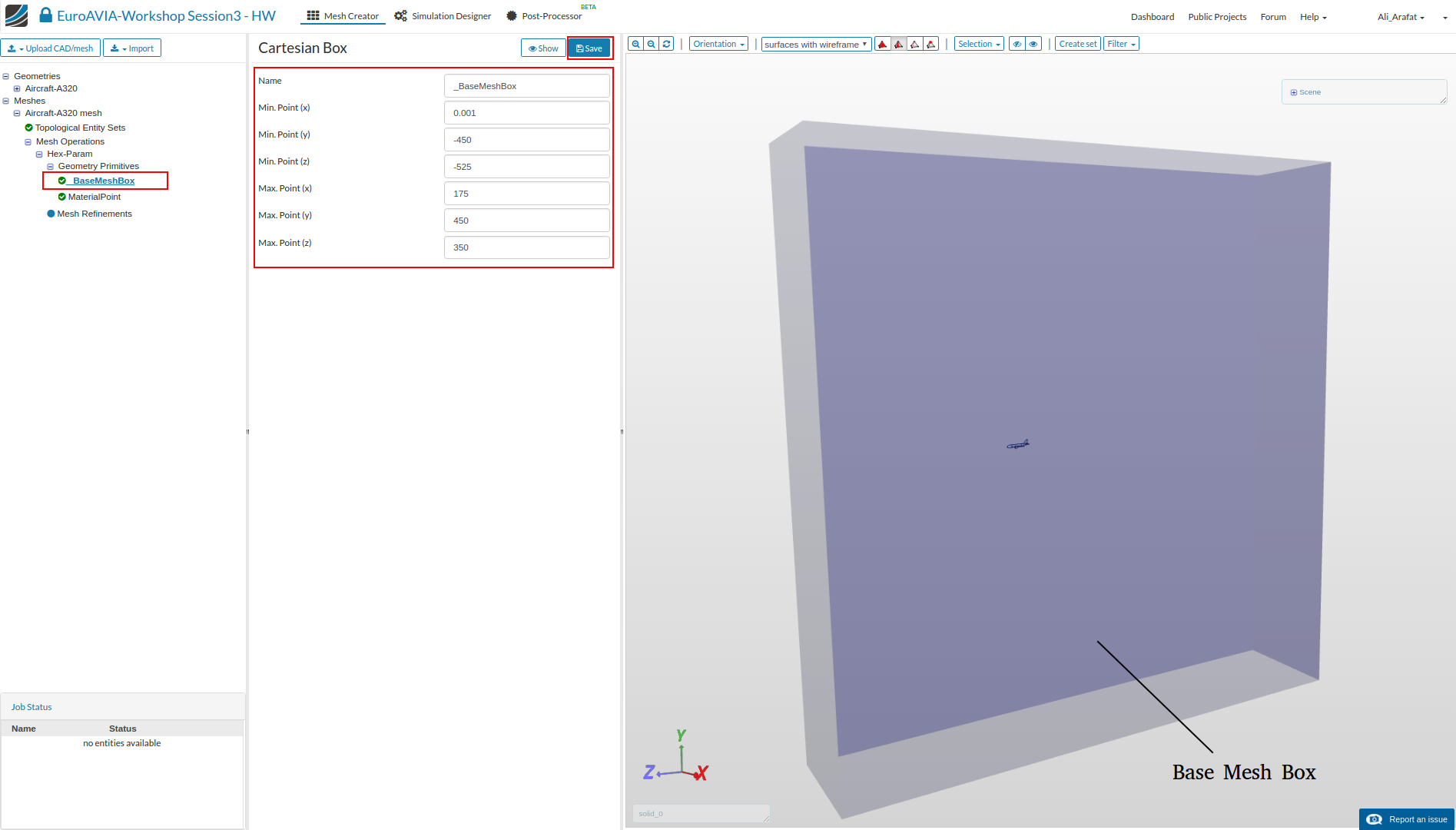
Base Mesh Box
The ‘Base Mesh Box’ defines the outer flow domain boundaries. This must be significantly larger for external flow. Enter the values as shown and click Save.
Min X= 0.001
Min Y= -450
Min Z= -525
Max X= 175
Max Y= 450
max Z= 350
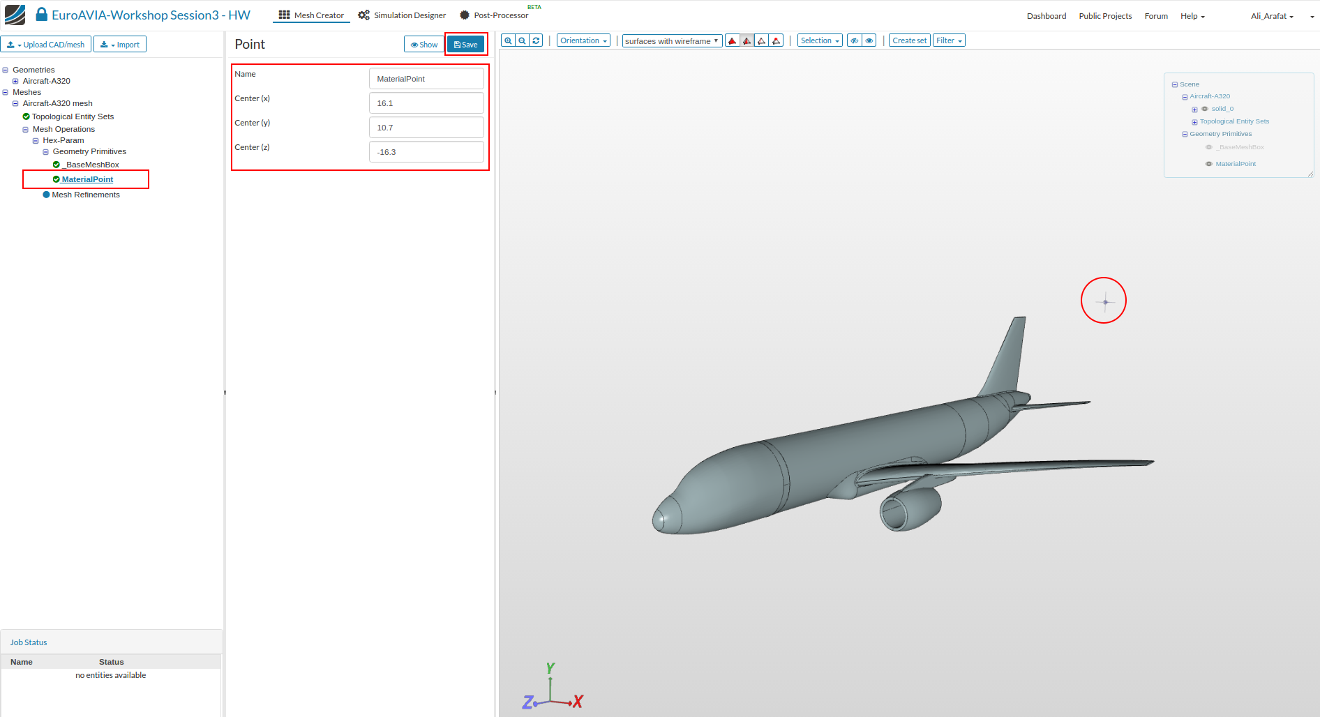
Material Point
The ‘Material Point’ specifies the region that will be meshed. So in this case the point must be out side the aircraft body.
Enter the values as shown and click Save.
Center X= 16.1
Center Y= 10.7
Center Z= -16.3
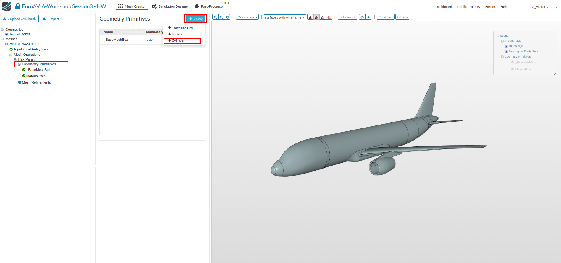
Further primitives
- We will create 4 entities that will be used for mesh region refinements later in the meshing setup.
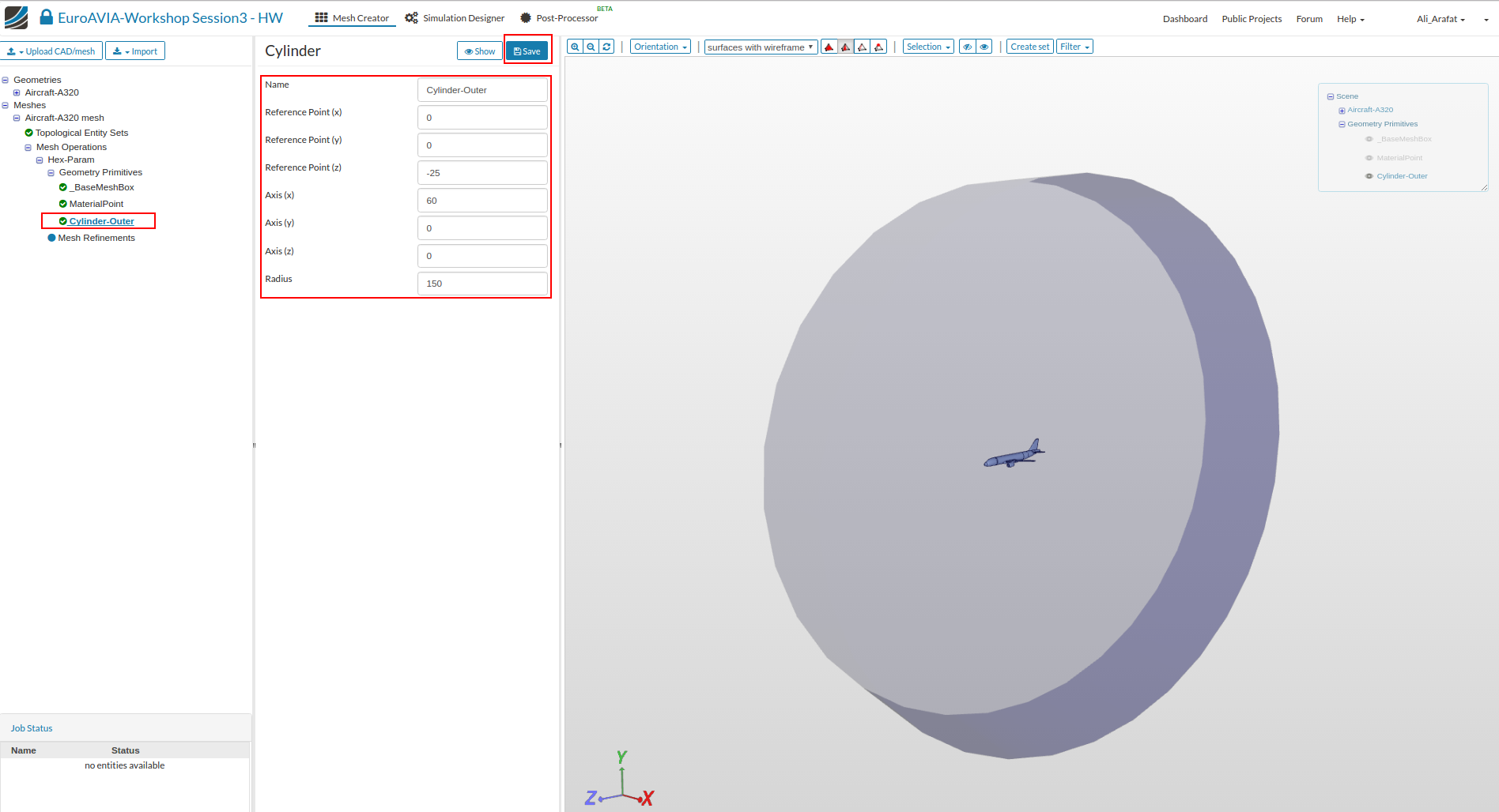
- To create a New entity, click on ‘Geometry Primitives’ and then the ‘New’ button on top to select a ‘Cylinder’ entity.
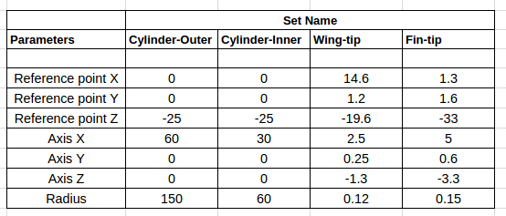
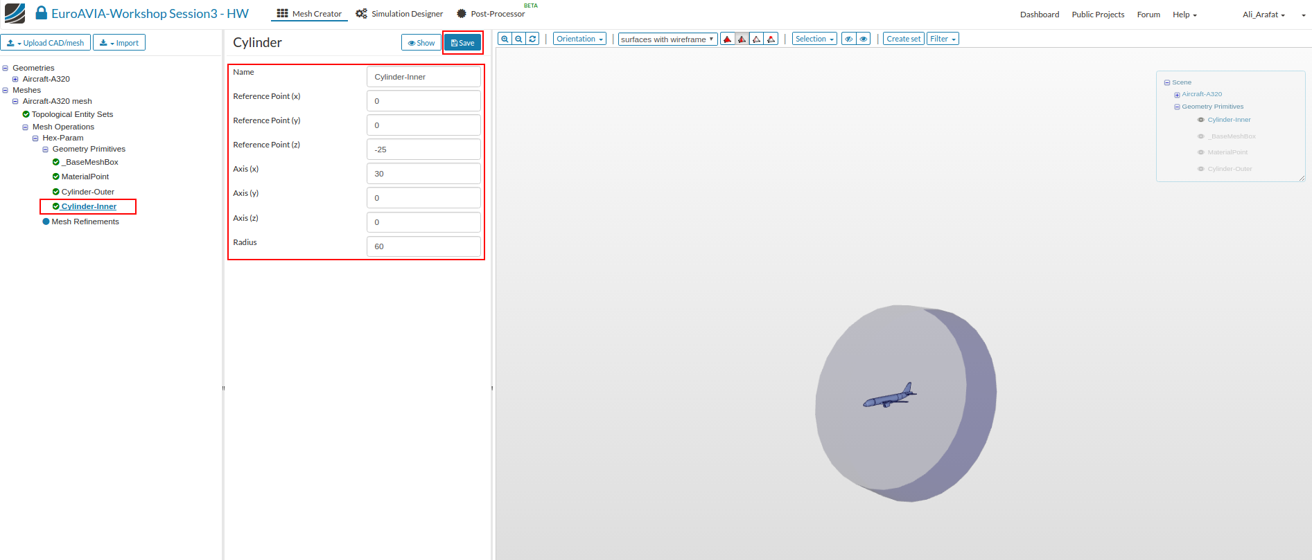
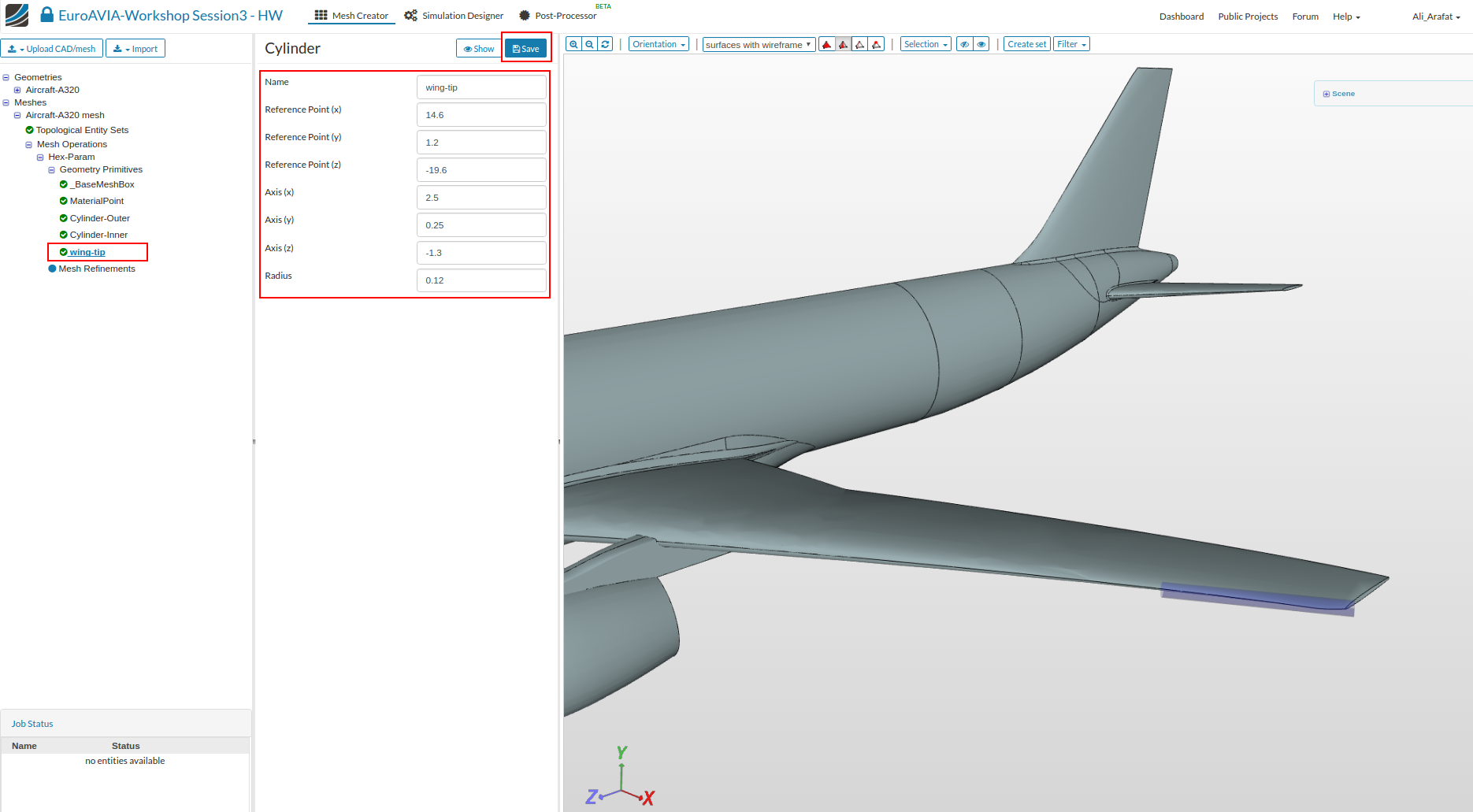
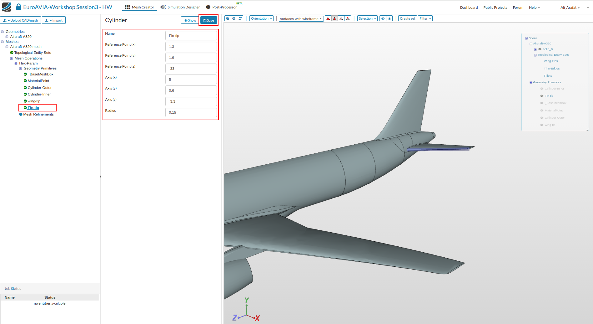
The table details the parameters for the 4 cylinder entities that are shown in the figures below.
.
Cylinder Outer
Cylinder Inner
Wing tip
Fin tip
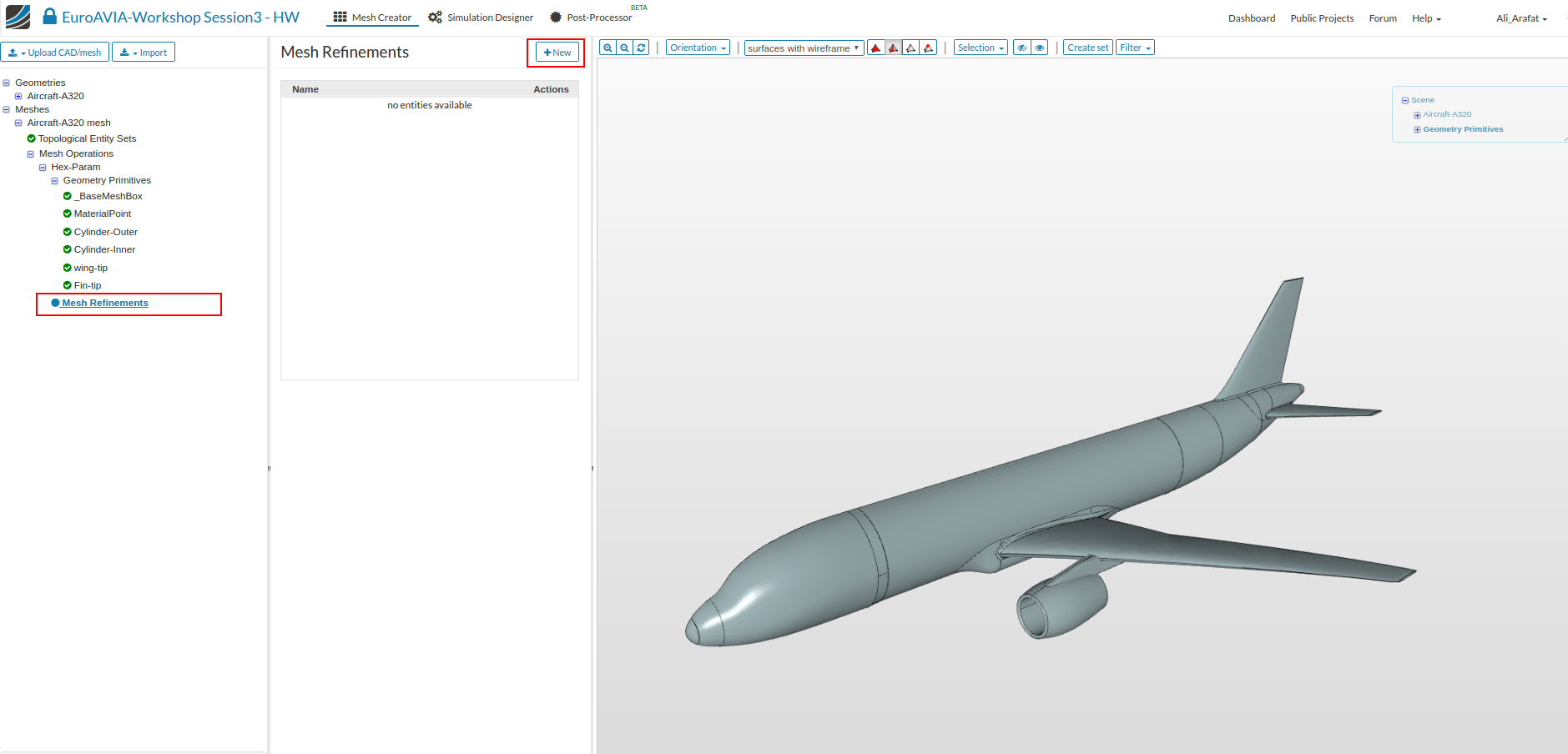
Mesh Refinements
We will now add the necessary mesh refinements for the previously created geometry sets and the geometry primitives.
- Click on ‘Mesh Refinements’ and click ‘New’ button to add a refinement.
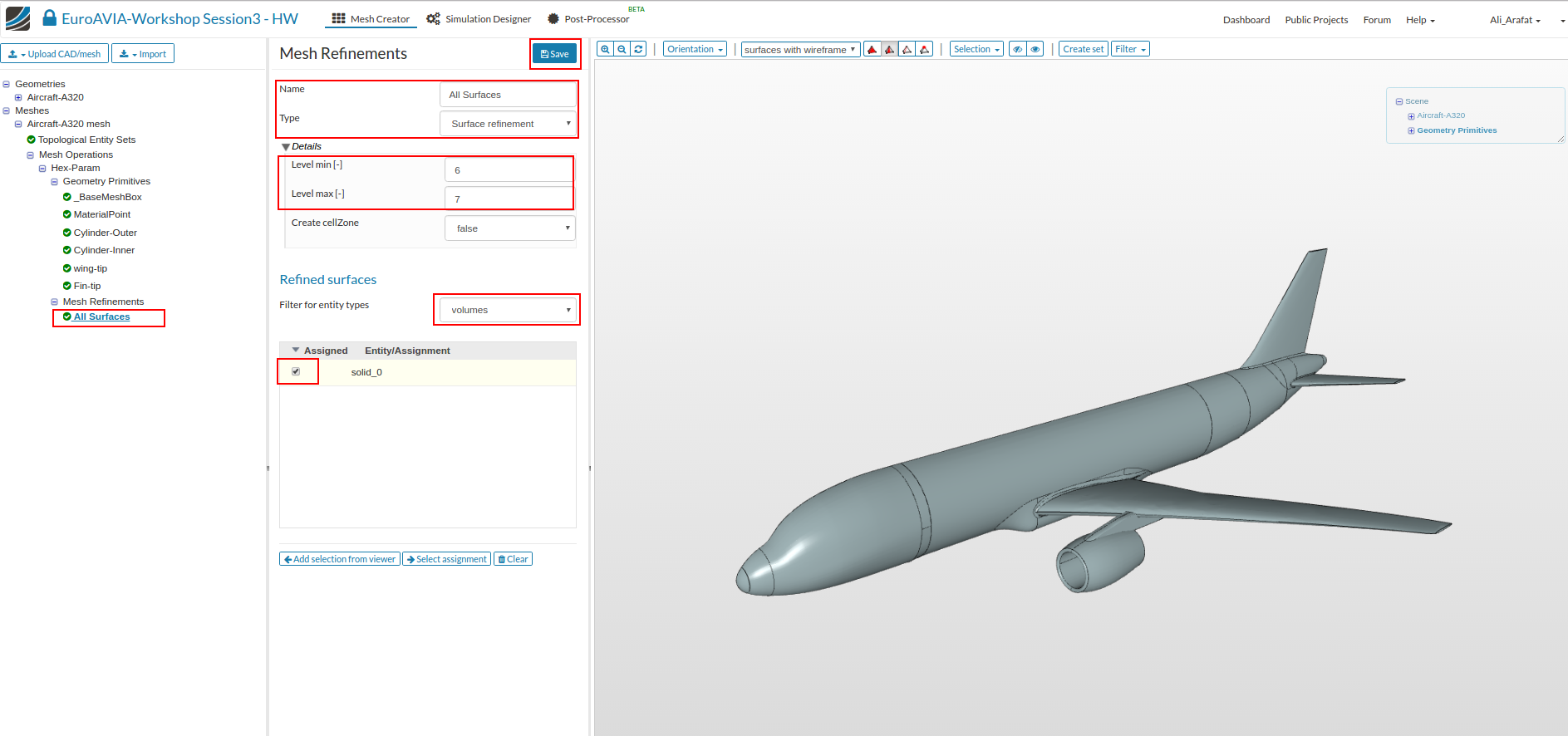
Surface refinements
- This refinement will used to refine the surfaces for the complete solid geometry.
Select the settings as follows and click Save.
Name: All Surfaces
Type : Surface refinement
Level Min : 6
Level Max : 7
Assigned entity Type: Volume
Name: ‘solid_0’
.
- This refinement will used to refine the surfaces for the existing face Set named ‘Wing-Fins’.
Select the settings as follows and click Save.
Name: Surf- Wing-fins
Type : Surface refinement
Level Min : 7
Level Max : 7
Assigned entity Type: Face sets
Name: ‘Wing-Fins’

.
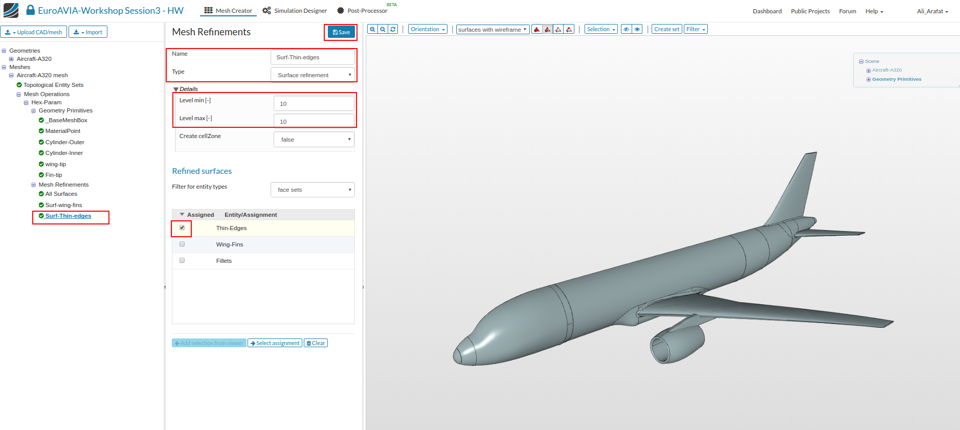
- This refinement will used to refine the surfaces for the existing face Set named ‘Thin-edges’.
Select the settings as follows and click Save.
Name: Surf - Thin edges
Type : Surface refinement
Level Min : 10
Level Max : 10
Assigned entity Type: Face sets
Name: ‘Thin-edges’
.
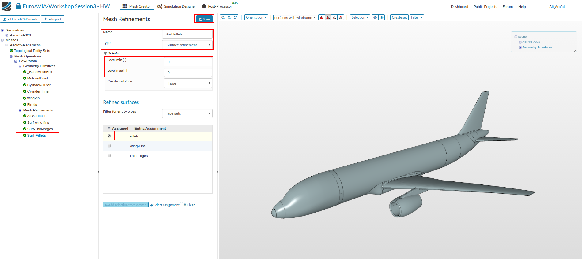
- This refinement will used to refine the surfaces for the existing face Set named ‘Fillets’.
Select the settings as follows and click Save.
Name: Surf-fillets
Type : Surface refinement
Level Min : 9
Level Max : 9
Assigned entity Type: Face sets
Name: ‘Fillets’
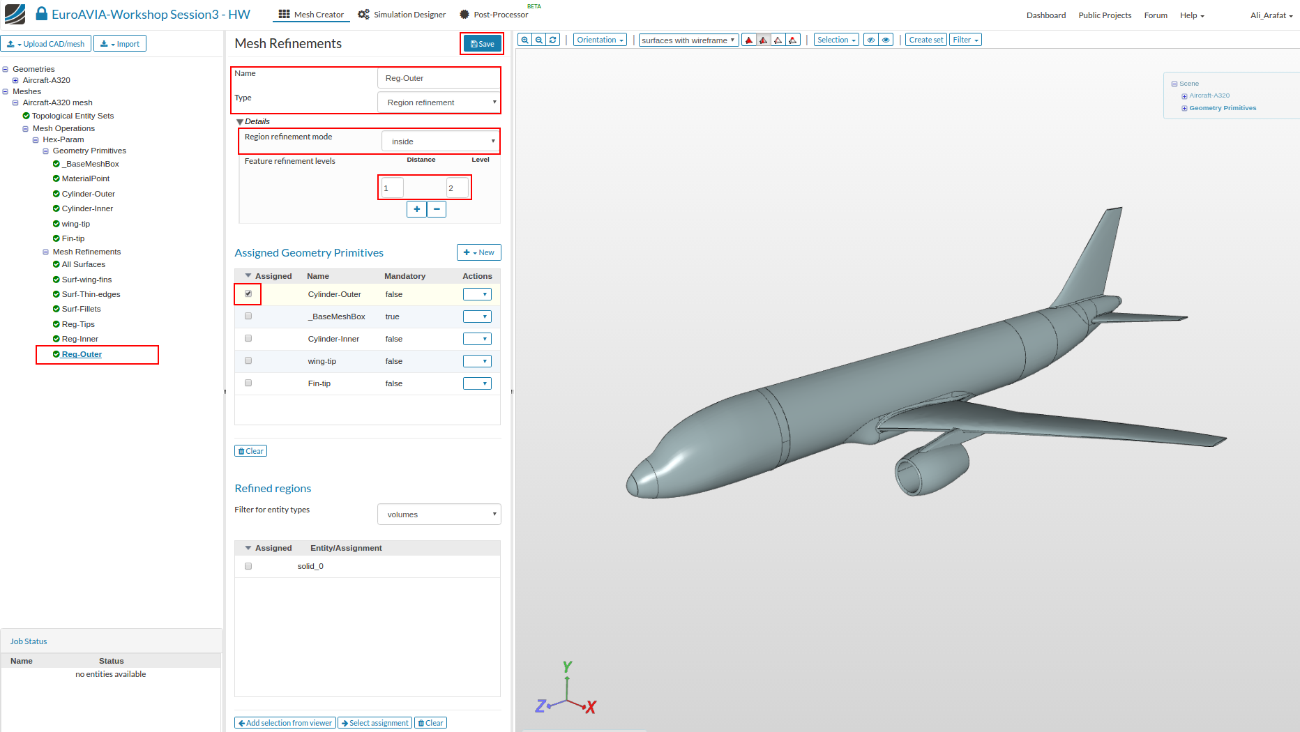
Region refinements
These refinements will refine the volume mesh. We will create 3 region refinements and assign them the previously created geometry primitives.
- So create a new ‘Mesh Refinement’ .
- and enter the settings as follows:
Name: Reg-Tips
Type : Region refinement
Mode : Inside
Distance : 1
Level : 9
Assigned geometry primitives: Wing-tip , Fin-tip

.
Name: Reg-Inner
Type : Region refinement
Mode : Inside
Distance : 1
Level : 3
Assigned geometry primitives: Cylinder-inner

.
Name: Reg-Inner
Type : Region refinement
Mode : Inside
Distance : 1
Level : 2
Assigned geometry primitives: Cylinder-Outer
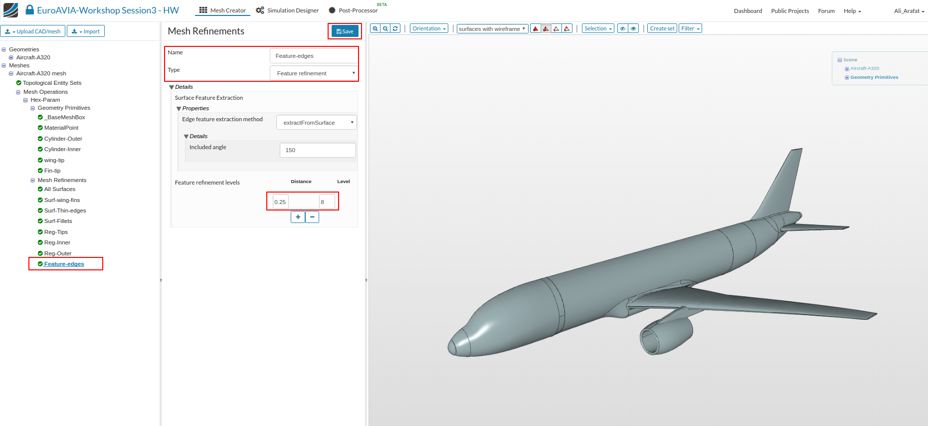
Feature refinement
The feature refinement will refine near edges. This is important to capture sharp corners.
- So Add a New ‘Mesh Refinement’, and choose Type as ‘Feature Refinement’. Give a Distance of 0.25 and a Level of 8.
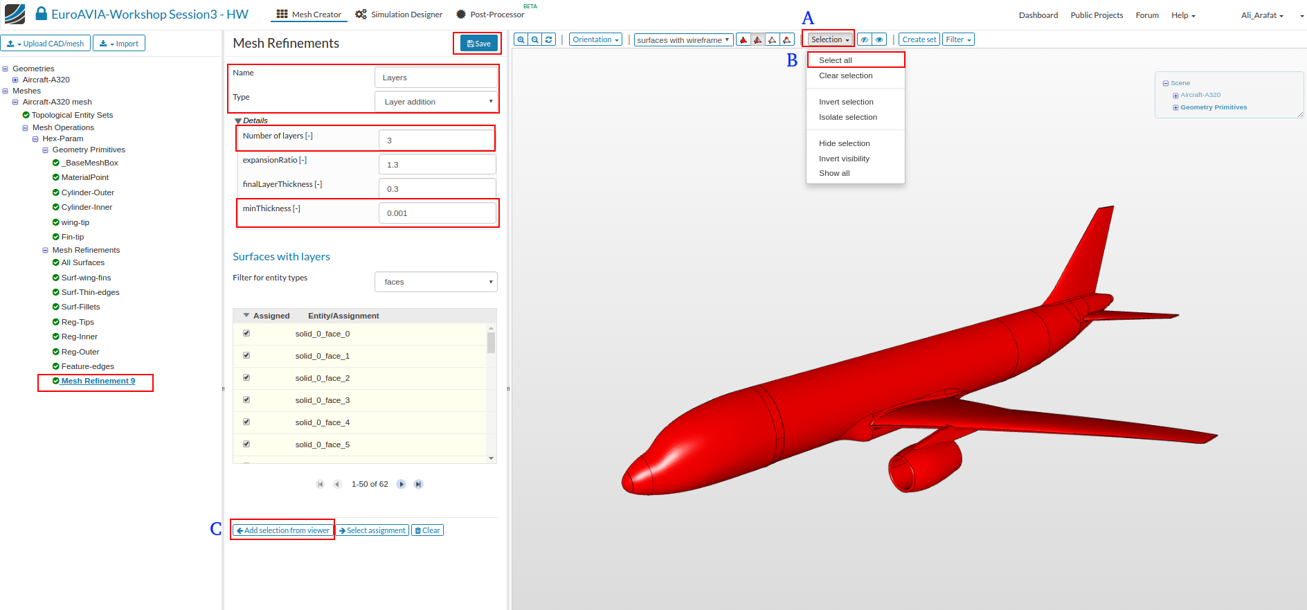
Layer refinement
The layer refinement is important to capture the boundary layer near the wall. This will create layer cells following the surface curvature near the walls.
- So Add a New ‘Mesh Refinement’, and choose Type as ‘Layer Refinement’. Change ‘Number of layers’ to 3 and ‘minThickness to 0.001’
- Then to select all the surfaces, click the ‘select’ button in the viewer tool bar [A], click ‘Select all’ [B] and then click ‘Add selection from viewer’ button [C] in the settings panel and click Save.
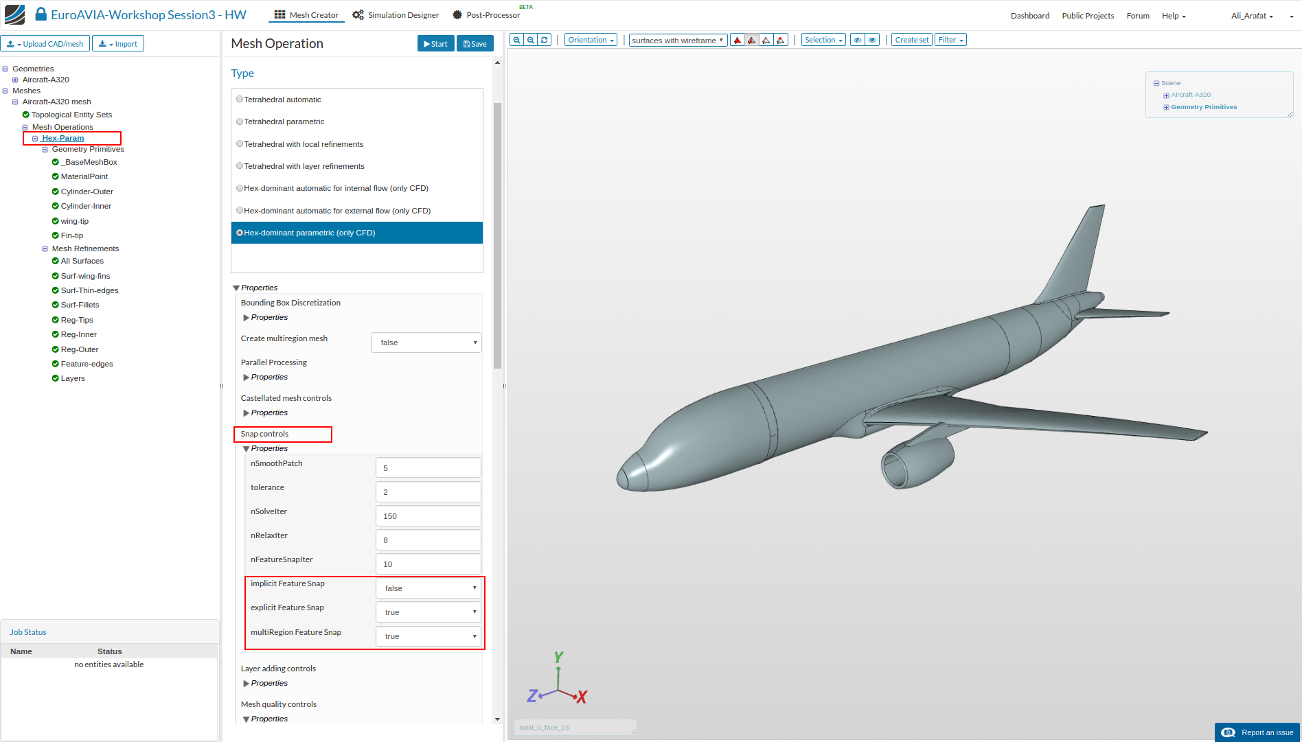
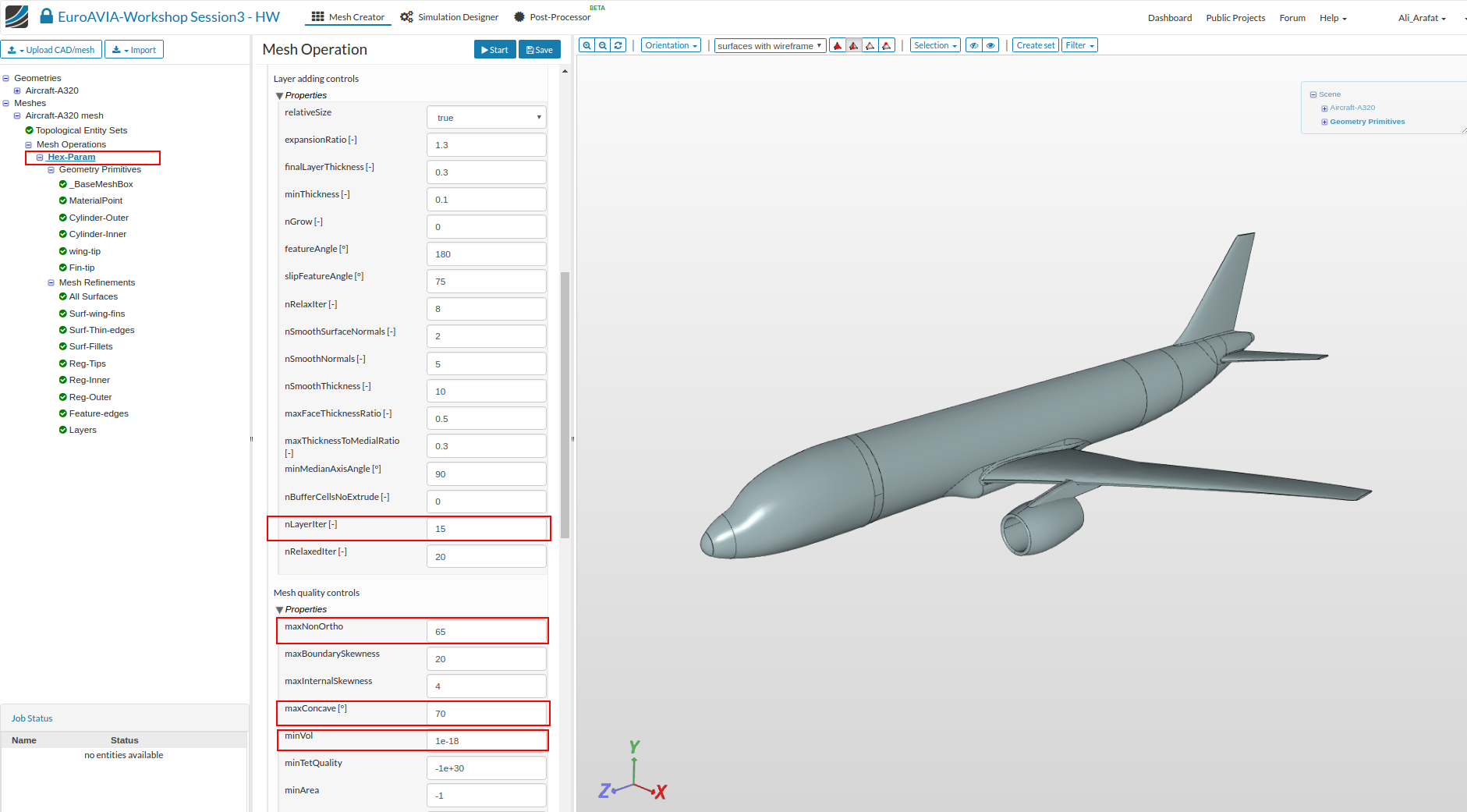
Some Advance settings
Lastly, we will change a few parameters in the Advance Settings by clicking on the mesh operation and scrolling in the settings panel as shown in figures below. This will help to get a good quality mesh for a complex geometry.
- Only the highlighted parameters need to be changed to the shown value.
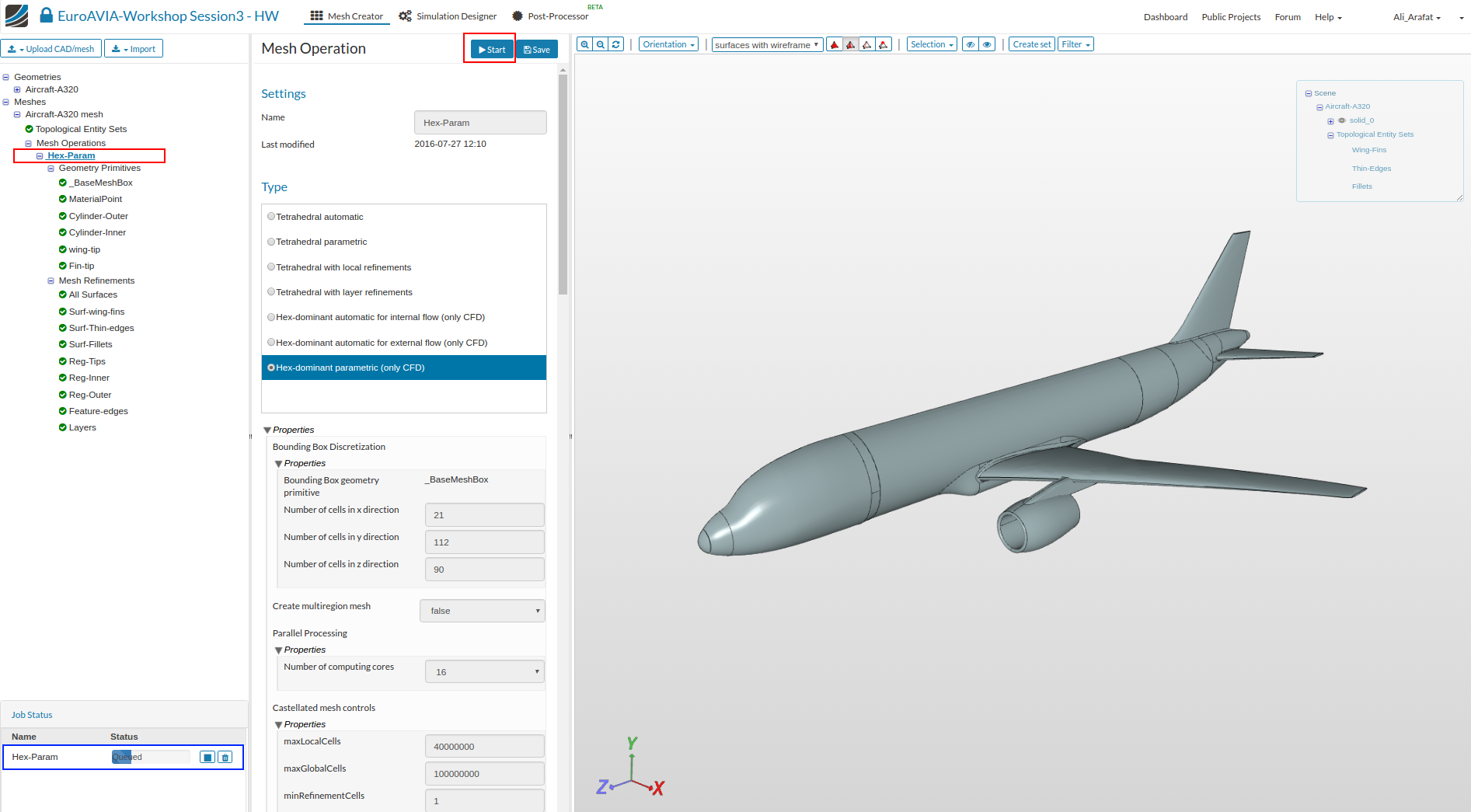
Start the Meshing Operation
Finally, click Save then to Start the mesh operation click on the Start button at the top.
Mesh-2 (close to the ground)
- For the second mesh, start by making a ‘Duplicate’ of the first mesh by right-clicking and selecting ‘Duplicate’.
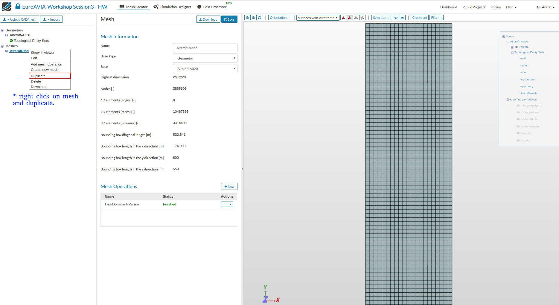
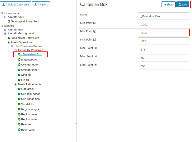
-
Next, change the ‘Base Mesh Box’ dimension of ‘Min Y’ to -3.65 and click Save.
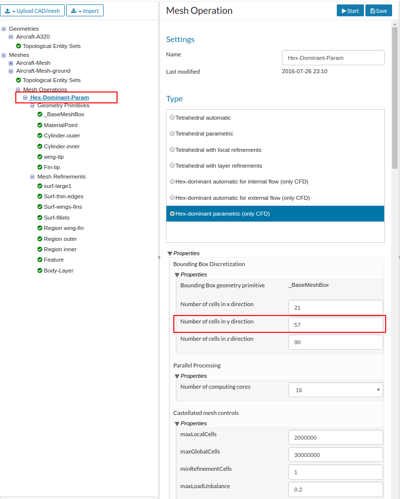
-
As the domain is now shorter in the Y-direction, we will adjust the base cell size under the ‘Main Settings’ by changing ‘Number of cells in Y-direction’ to 57.
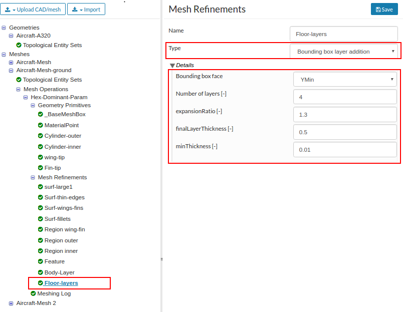
- Lastly, we will add a New mesh refinement of type ‘Bounding box layer addition’ to add a layer mesh to the ground floor. So enter the following values:
Bounding box face : Y Min
Number of layers : 4
expansion ratio : 1.3
finalLayer Thickness : 0.5
minThickness : 0.01
- That’s all. Once done click the ‘Start’ button to begin the meshing operation.
There will be a warning message saying that the previous mesh result ( the duplicated one) will be deleted. That is OK, so just click yes and continue.

