Link to part 1 of the tutorial:
FSAE Trackside Aerodynamics - Session 1 - Yaw Angle Analysis (Part 1)
Introduction
Welcome to the second part of the step-by-step tutorial for the simulation of a Formula SAE full car with side wind. In this part of the tutorial we will show you the final steps for the simulation setup and we will go over the post processing of the results. Like last session, we will also go through some of the results and what they mean.
Simulation Setup (Part 2)
Numerics
After defining all the boundary conditions, we will proceed to set up the numerics for our simulation.
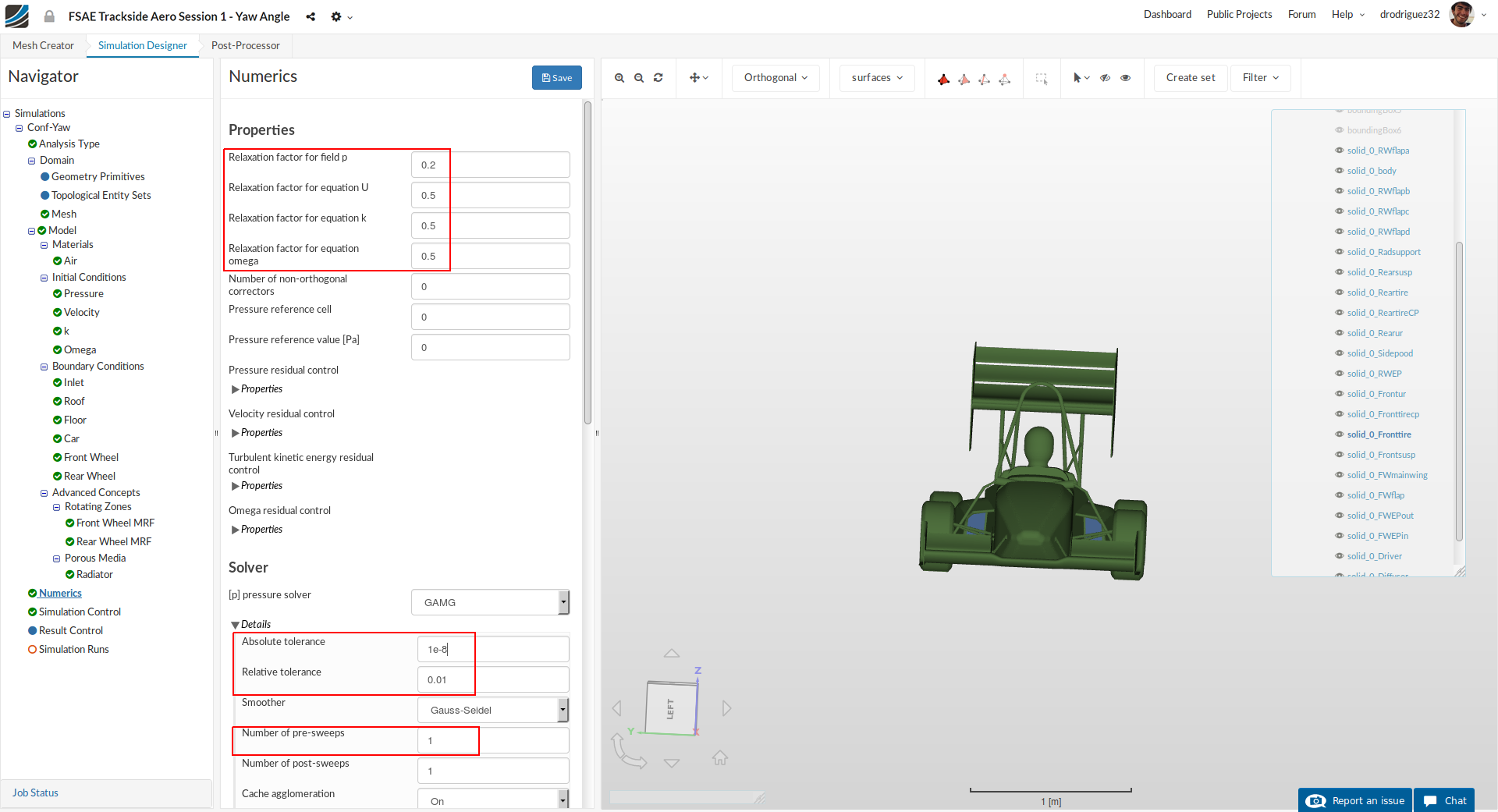
Go to Numerics and change:
-
Relaxation factor for field p, Relaxation factor for equation U, Relaxation factor for equation k and Relaxation factor for equation omega to 0.2, 0.5, 0.5 and 0.5 respectively.
-
Furthermore, under [p] pressure solver, change Absolute tolerance, Relative tolerance and Number of pre-sweeps to 1e-8, 0.01 and 1 respectively.
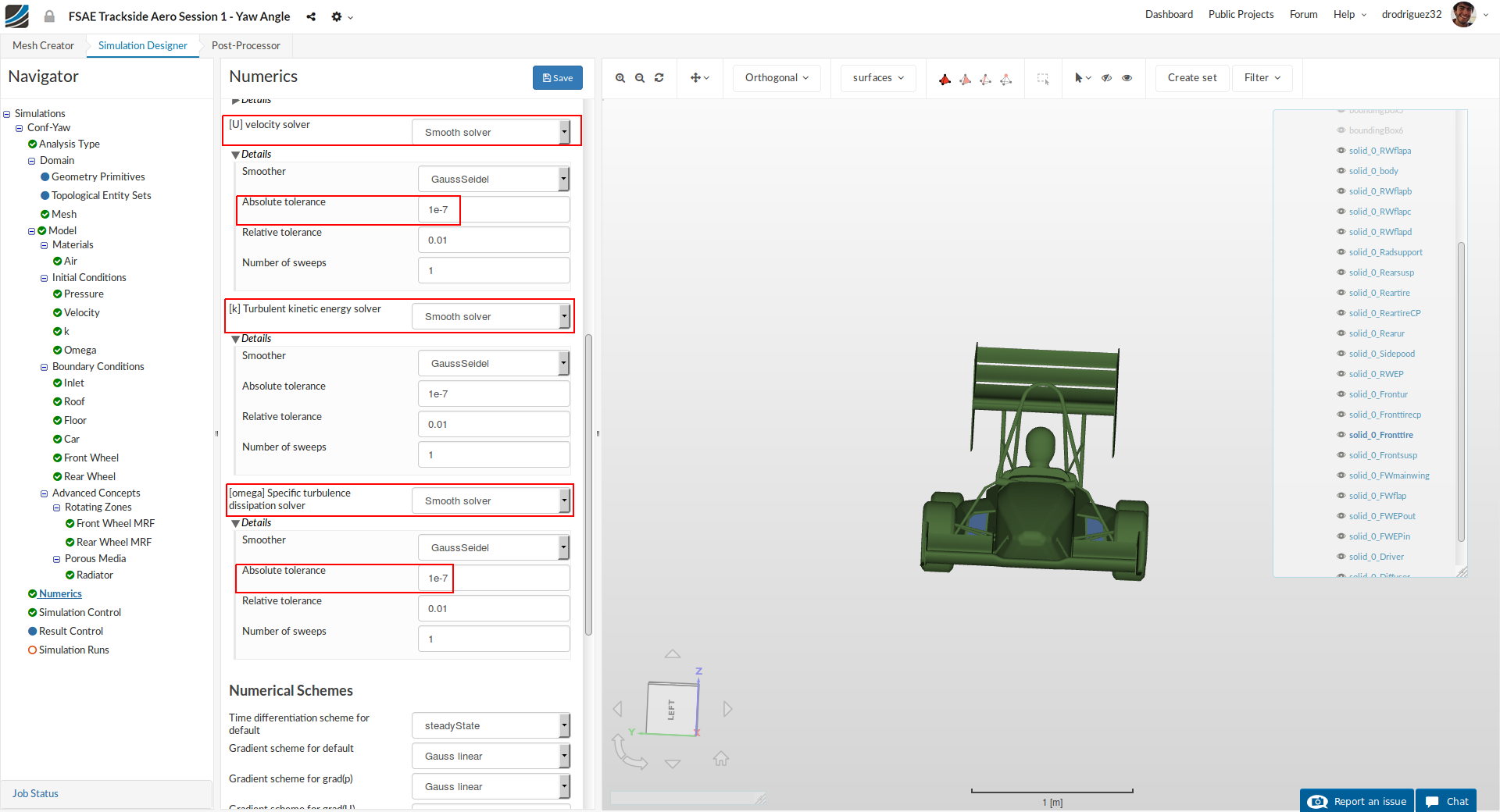
Scroll down until [U] velocity solver and change:
- [U] velocity solver to Smooth solver, Smoother to symGaussSeidel and Absolute tolerance to 1e-7. Do the same for [k] Turbulent kinetic energy solver and [omega] Specific turbulence dissipation solver
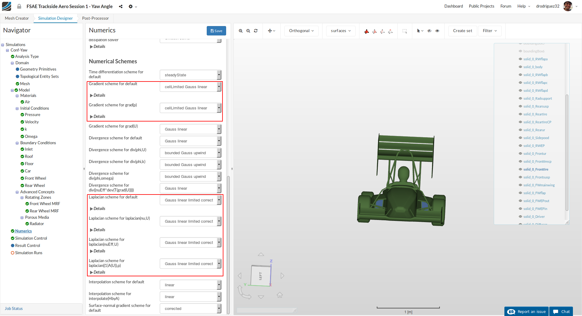
Scroll down to the end and change:
-
BothGradient scheme for default and Gradient scheme for grad(p) to cellLimited Gauss linear
-
Laplacian scheme for default, Laplacian scheme for laplacian(nu,U), Laplacian scheme for laplacian(nuEff,U) and Laplacian scheme for laplacian((1|A(U)),p) to Gauss linear limited corrected
-
Click Save to register all of your changes.
Simulation Control
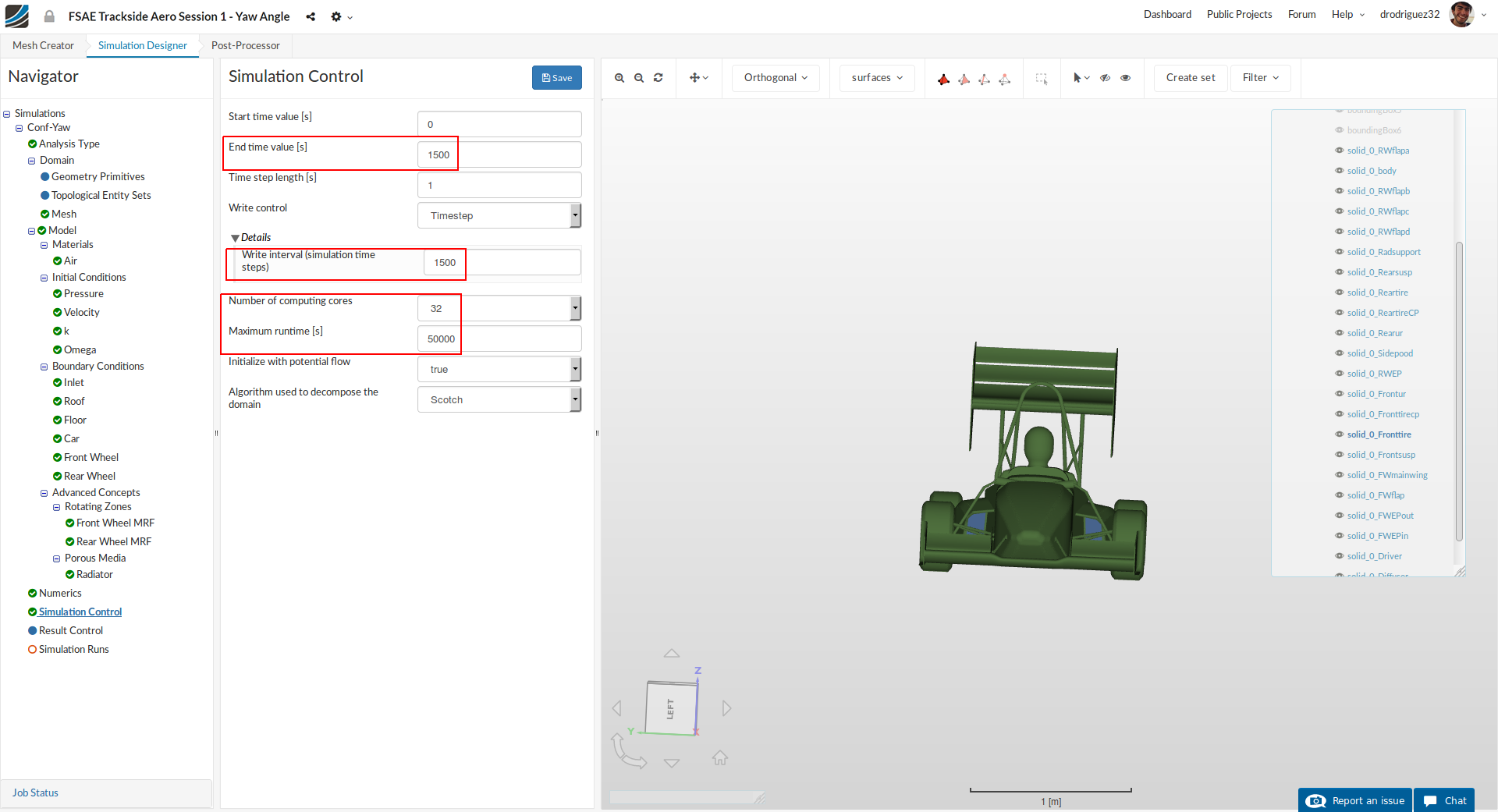
For the simulation control we will specify the End time value [s], Number of computing cores and Maximum runtime [s] to 1500, 32 and 50,000 respectively. Also, under Write Control > Details change the value to 1500.
Result Control
As the last step before starting our simulation run, we will create result control items in order to obtain graphical data of the results.
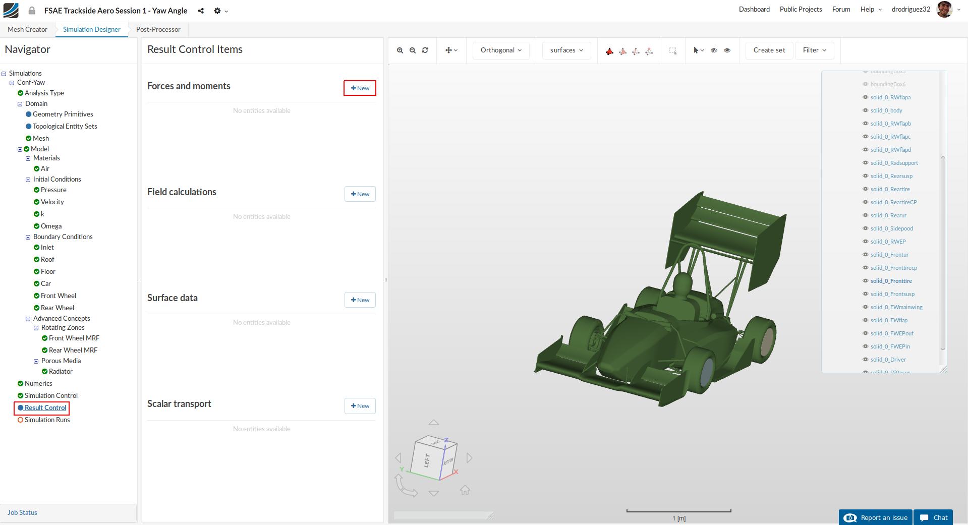
Go to Result Control and click +New next to Forces and Moments.
1. Front Wing
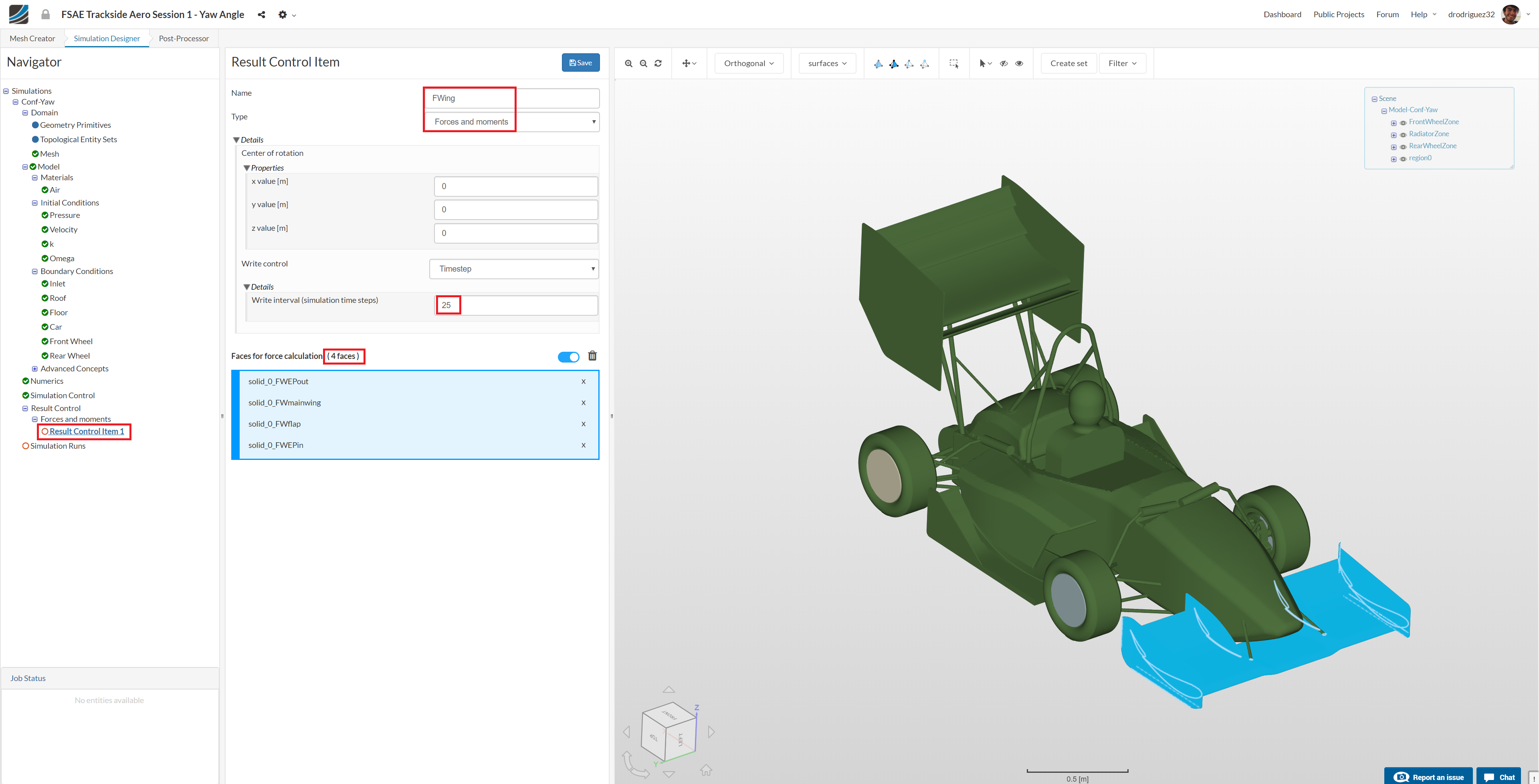
A new Force and Moment result control item will be created. Rename it to FWing (optional).
Change the Write interval (simulation time steps) to 5
Select solid_0_FWmainwing, solid_0_FWEPin, solid_0_FWEPout and solid_0_FWflap, you should see them under Faces for force calculation.
Click Save to register your changes.
2. Rear Wing
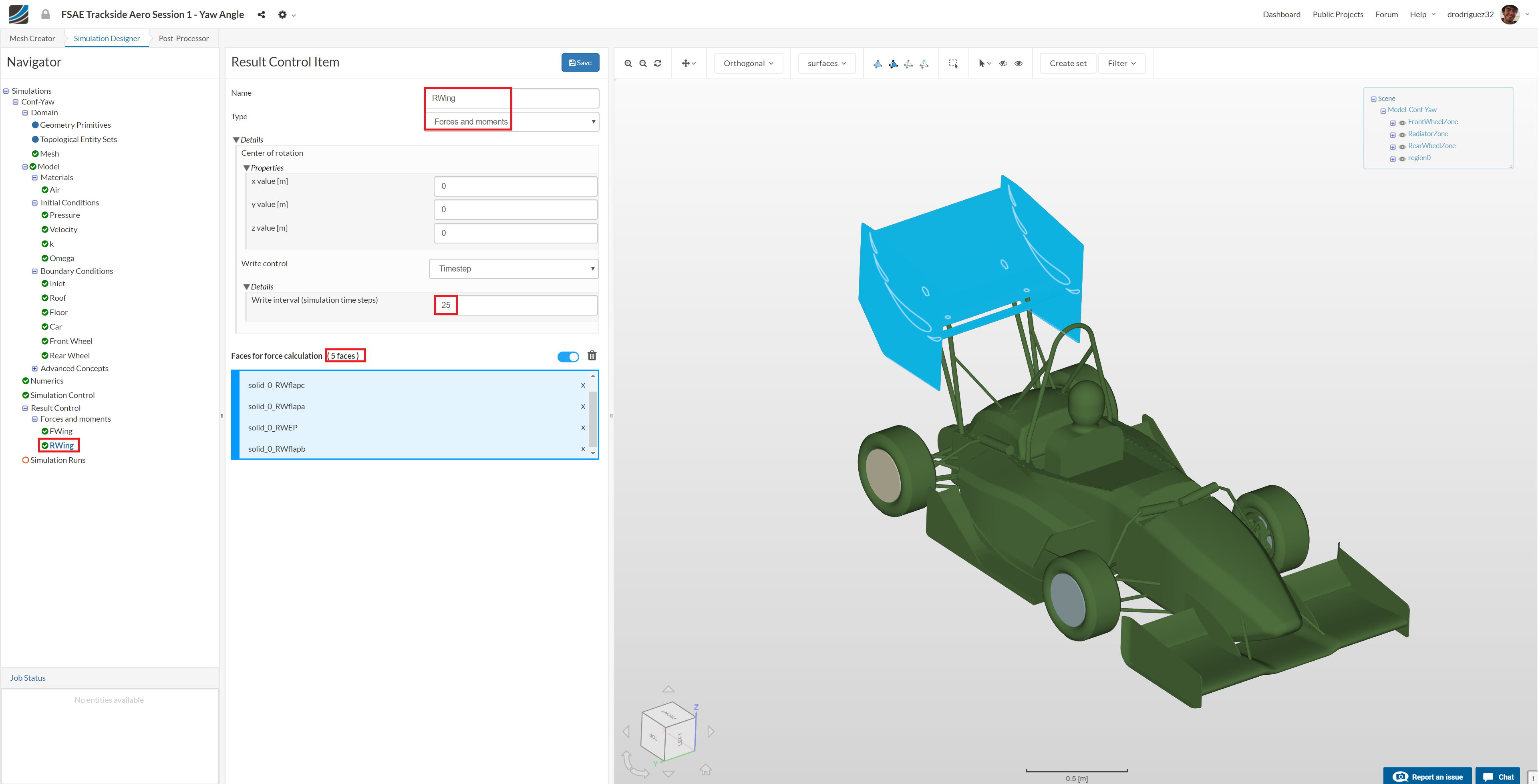
Create a new Force and Moment result control item for the rear wing. Rename it to RWing (optional).
Change the Write interval (simulation time steps) to 5
Select solid_0_RWEP, solid_0_RWflapa, solid_0_RWflapb, solid_0_RWflapc and solid_0_RWflapd, you should see them under Faces for force calculation.
Click Save to register your changes.
3. Lift and Drag Coefficients
Now we will calculate the lift and drag coefficients for the entire car. For this, create a new Result Control Item, and under the drop down menu select Forces and moments coefficients
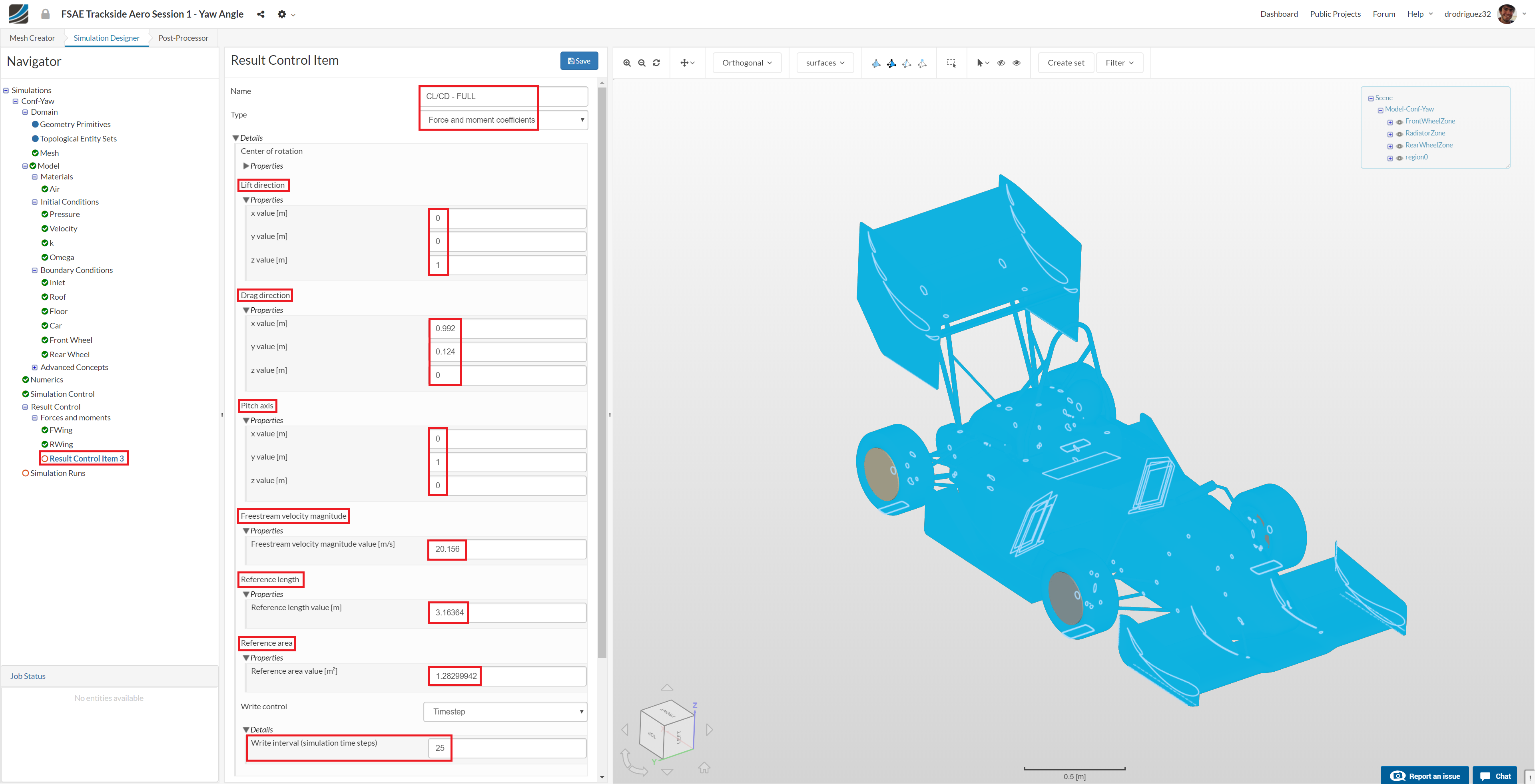
Leave the center of rotation at (0,0,0)
Change the Lift Direction to (0, 0, 1)
Change the Drag Direction to (0.992, 0.124, 0)
This vector was found using the yaw angle. In this case X = cos(7.12) and Y = sin(7.12)
Change the Pitch Axis To (0, 1, 0)
Change the Freestream Velocity to 20.156
This was found using the side wind magnitude and straight line speed of the car: 20.156 = \sqrt{20^2+2.5^2}
Change the Reference Area to 1.28299942.
Change the Reference Length to 3.16364
If you want to use different side wind magnitudes, use the values in the following table:
| Side-Wind Vel. [m/s] | Yaw [^{\circ}] | Freestream Vel. [m/s] | Ref. Area [m^2] | Ref. Length [m] |
|---|---|---|---|---|
| 2.5 | 7.12 | 20.156 | 1.283 | 3.164 |
| 5 | 14.04 | 20.615 | 1.435 | 3.236 |
| 7.5 | 20.56 | 21.360 | 1.577 | 3.353 |
Simulation Run
Once all the above steps are defined, we will proceed to create our first simulation run.
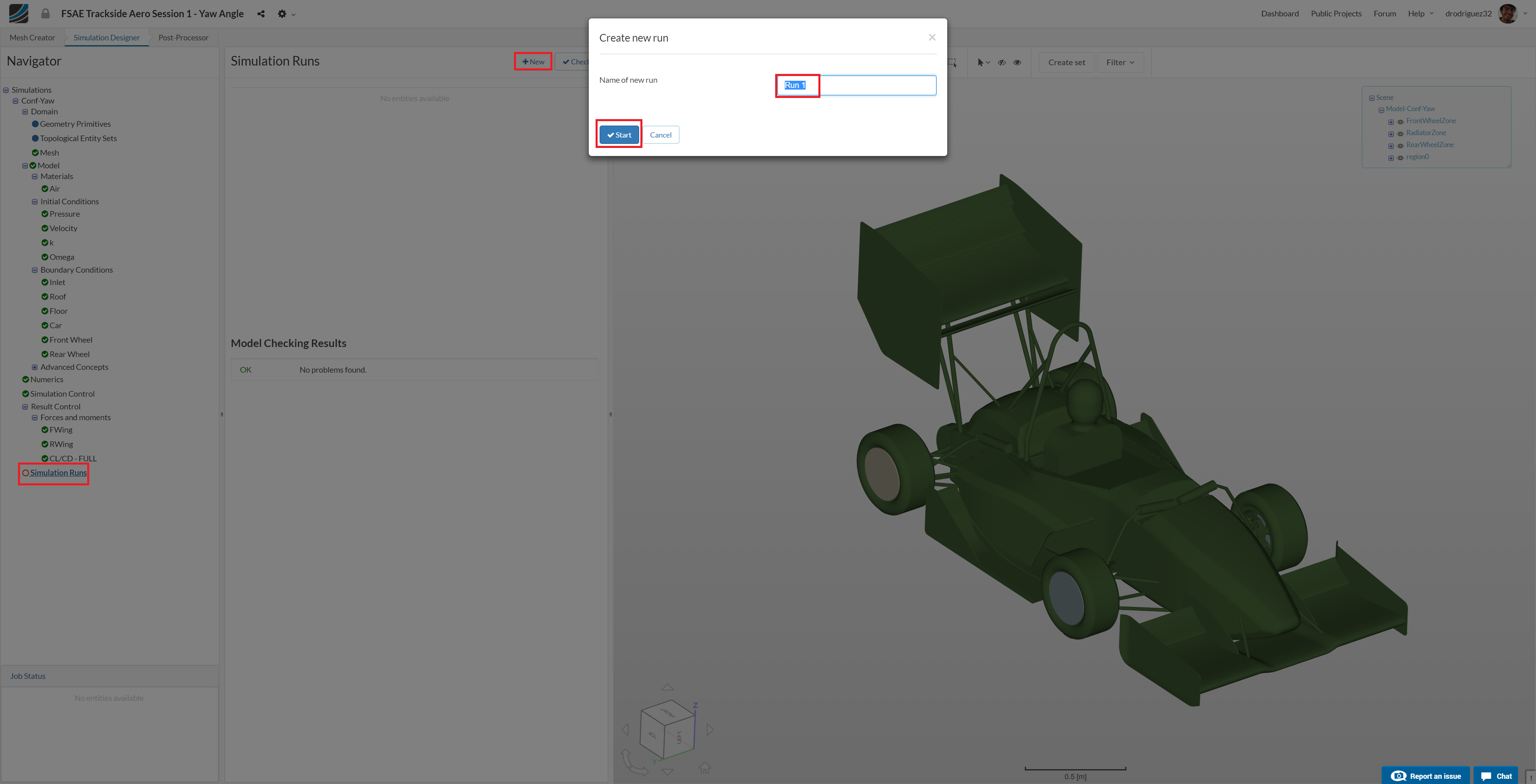
Go to Simulation Runs and click on +New. A window will pop up, give a reasonable name to the run e.g. Run-conf-Yaw in this case (optional) and click Create in order to create a new run.
After the run is created, click Start to start the created run. The simulation run can take up to ~190 minutes (~3 hrs.)
Homework Submission
For your homework, your task is to investigate the full car running in a straight line at 20 m/s with side wind. You will have the same model we used for the last session, so you will setup porous media, MRF (rotating) zones, rotating walls, and the flap angle will be 0 degrees. In particular you will focus on studying the impact of the side wind on drag and lift coefficients.
The step-by-step tutorial below contains all of the steps for setting up the simulation in SimScale and visualizing the results.
Homework Deadline: XXXXXX, 11:59 pm CEST
Click Here to Submit your Homework
Results on SimScale
When your simulations are finished and you go to the Force Coefficient Plots in the Post-Processor, please just look at the ones called Lift Coefficient and Drag Coefficient. These are the C_L and C_D we’ve been taking about in the tutorial and the ones we’re interested in.
Results
For the C_L and C_D charts click on the following link: