they tend to all time out but the drag output results look steady, especially in my latest oine run without any turbulance model was steady at 600N of drag, the one termed 70 mph turbulance reduction
I’ll copy your project and do a few runs.
Kind regards,
Darren
i also did notice on the last run that it was only 4 cores so it timed out unusually early but thanks for the hel, i should expect somewhere in the region of 200-300n of drag for the Cd value to match reality
@Lemlurker I would add layers to the mesh, define the walls as no-slip/wall function and add a turbulence model. I think you need to be looking at parametric meshing as you would have more control over refinement. Adding layer inflation and surface refinement to the car and leaving the rest of your mesh corse would save you a lot of core hours.
I think we need to start here to rule out issues from the mesh. And I know above you said that you tried making the mesh bounding box larger but I would recommend making it larger still a general rule someone once said to me was 5 times the dimension of the object in each direction and 15 times in the flow direction. If this doesn’t work at least we shall have a very good mesh to start.
Kind regards,
Darren
1 Like
i started out running it with turbulance model and no slip vehicle walls lol, but ill definitly try somt of the other parts
Hey guys,
I’m dealing with kind of the same issue. I want to validate drag force of a sphere and with manual mesh I get twice the value I expect.
And as I was thinking about it, the memory popped my mind that a year before @AsadAli has solved a similar case for me. My bad, I haven’t really went through his solution to compare with my setup but I’ll do it and report my findings.
The thread can be found here:
My current project is here:
The funny thing, with very fine mesh I get exact values (approx. 10% error) but it took 84mins. The automatic mesh came with double drag force. But I also reduced the boundary box so maybe that is the thing in my case.
Anyway, I’ll investigate it and will come back to share what I found.
Have a nice day,
János
1 Like
thanks for the info, ill take a look and give this a go
do ou have a link to the threead since it seems to be to your project instead
Sorry, this one:
thanks
The STL is consisting of a single surface so snappyHexMesh is unable to create any boundary layers; that’s the issue. You need to split the model either manually in your CAD software or automatically split the STL by angle within SimScale.
This also explains the yPlus images you’ve been showing. As there are no constant height layers, only snapped hexas, you are getting those unconsistent values.
by split it in the cad do you just mean a different object? also how do i split per angle in simscale?
scratch that figured it out, whats the best way to edge split my mesh, by angle or manually by some other means?
If “by angle” doesn’t work, you can use any other tool of choice.
I would place the wheels in a different patch so that you can apply rotation to them. If you are not able to do so, I’ll try this weekend.
the software im using is blender, i know its not ideal for this application but is it just the case of splitting parts into a different object?
In your case the most convenient way would be to save, e.g., each wheel as a different STL. Then, you’ll have to merge each file into a single STL, for which you may follow this Formula Student workshop from SimScale.
I forked your project a couple months ago, and there I split you model. You can check it here:
I also found that the automatic mesh (back then) didn’t create boundary layers for the half-model. You may fork the project and use the manual mesh for your simulation and see how it goes.
Hi guys,
I was playing around a bit this weekend and there’s something I found:
I don’t know wether it is a wise thing to do but I found that you can use Slip walls instead of Pressure outlet boundary condition in simple cases. I mean in my current project where I simulate flow around a sphere (https://www.simscale.com/workbench?publiclink=ae4d6967-4840-4f82-a1a3-a38b0aa8b052) I had a setup with 1 inlet, 1 outlet, 4 slip walls and 1 inlet, 5 slip walls as well. The results and the runtime were identical in each cases.
These are my findings regarding to this topic:
-With Hex-dominant automatic mesh generation the drag force is:
- accurate (37% error with moderate, 13% with very fine mesh) at Re=10^2 (laminar) flow
- around twice as much as calculated at Re=10^6 (turbulent) flow
-With manual mesh (by trying to implement similar approach like @AsadAli used in the Parachute project)
- around twice as much as calculated at Re=10^2 (laminar) flow
- accurate (32% error with moderate mesh) at Re=10^6 (turbulent) flow
(The settings are identical only the velocity was changed from 0.00155 m/s (laminar) to 155m/s (turbulent))
@pfernandez; since my model is only a one-surface part I experimented with a split model based on your suggestion. The funny thing is that in the laminar case I expect for the drag force:
1.14e-6N
And with the split model I got:
7.17e-7N
In this case it is not twice the value but around half. ![]()
So with all this information this phenomenon gets more and more interesting for me. Although I tried I couldn’t find out what went wrong what should be done differently.
If some “more-experienced-than-me” CFD guy would review this topic I’m sure it’d be useful for all of us.
And for sure I’ll also investigate it further. ![]()
Best regards,
János
Hi János,
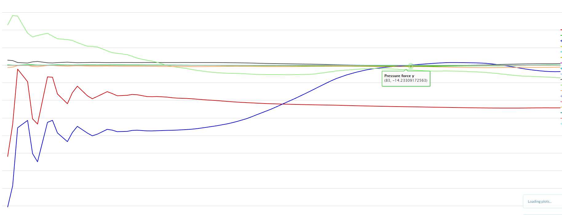
You have to add viscous and pressure forces to get total drag force.
So, in your case you would get a total drag of 1.463e-6 N.
By disabling turbulence, I got a drag value of 1.328e-6 N with your mesh.
Cheers.
1 Like
Hi Fernandez,
that was also my idea when I read about drag force on Wikipedia: “The aerodynamic forces on a body come primarily from differences in pressure and viscous shearing stresses. Thereby, the drag force on a body could be divided into two components, namely frictional drag (viscous drag) and pressure drag (form drag).”
[source: Drag coefficient - Wikipedia]
Then I found this video which explains how to extract drag and lift in ParaView: How to calculate aerodynamic forces with Paraview - YouTube
It was a bit confusing because here the viscous force is not taken into account. So I only calculated with the pressure force.
Now I propose that it is only neglected because at turbulent flow the viscous force is much smaller. But in our case -at this very low speed- it is significant.
So this split-model technique is really the way to go!
To prove it I checked the turbulent flow (Re=10^6) around sphere.
I expected drag coefficient of around 0.15 but I got 0.37 instead. Then I checked the graph of Cd in function of Reynolds number:
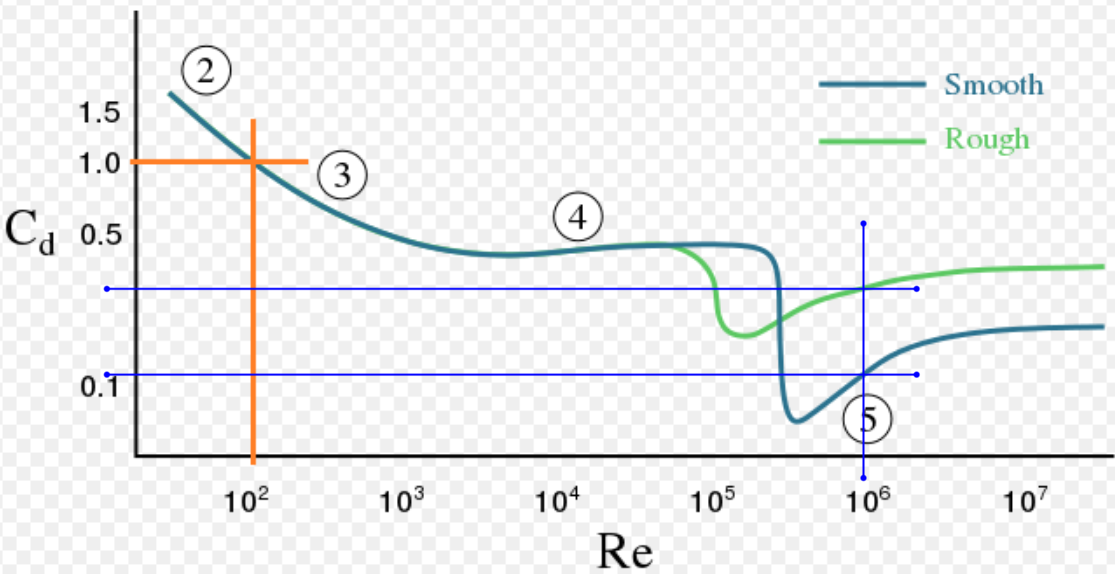
As you can see, the Cd for the rough sphere is just around 0.37!
With finer mesh and more computational effort I’m sure that the result would converge to the smooth’s values but I’m really satisfied with it!
So thank you Fernandez for the tips I learnt a lot! ![]()
Additionally: how did you know about this trick with splitting the surface? Is there any written documentation about it somewhere? When is it necessary and what is the best practice to split your model in CFD?
Best regards!
1 Like