Hi,
I am attempting a variety of meshing alg. on the DrivAer model. As recommended on a previous forum post (Unable to create a HexParametric/automatic Mesh having created a standard mesh), I have attempted a standard mesh as well as a Hex. The Hex mesh in general computes faster and is giving the lowest volume ratios. I was however wondering why the grid tends to refine towards the walls of the domain, including inlet and outlet boundaries? This is the case when using both the manual and auto Hex Mesh. Any insights/ suggestions can potentially help with reducing the computational times.
Mesh for reference: Mesh 7.1 and Mesh 8.2
Many thanks,
Aditya
Project link: SimScale
Hey there,
Automatic meshing algorithms refine the walls (and all boundaries for that matter) with two goals:
- To properly capture the geometry. And you can see this as optimization by using less refinement in regions far from the walls.
- To properly capture gradients, because at boundaries is where fields tend to change the most.
If someone else has something to add here, please go ahead!
Thanks for the prompt reply and yes I agree with the requirement for refinement near wall. However, far from the model, the far wall and the inlet boundaries tend show refinements as well? This is when using the Parametric Hex Mesh too.
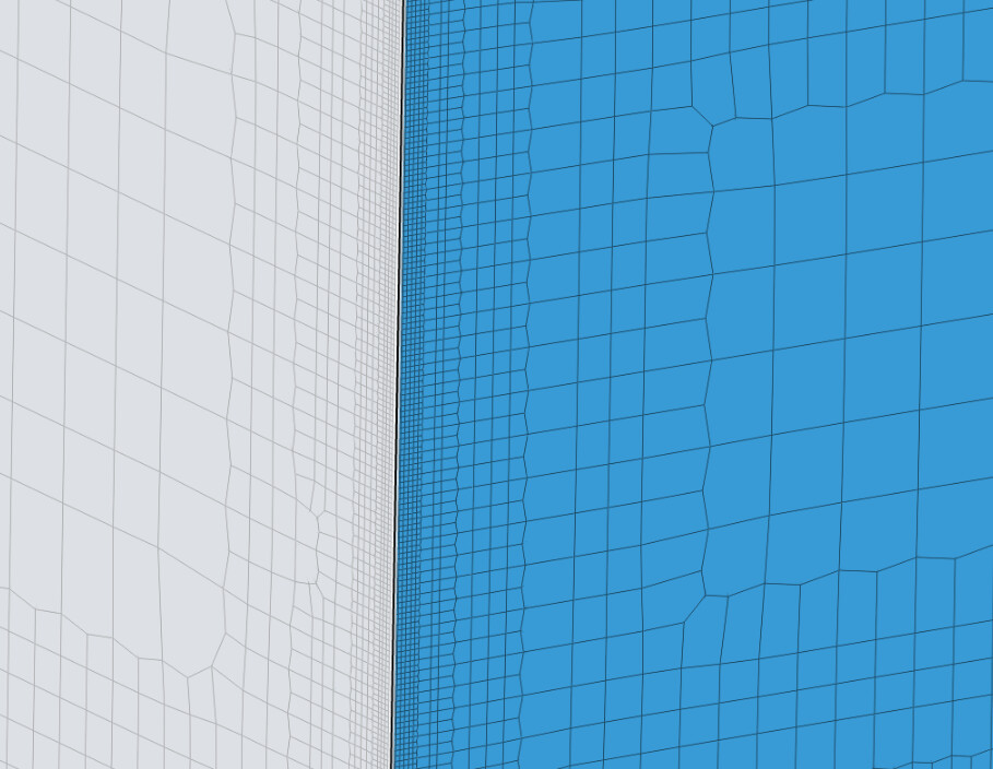
The surface in blue is the inlet boundary and highlighted in white is the far wall. There seems to be refinement towards these boundary edges. I understand the requirement for prism layers but this seemed unusual.
I was wondering if it was a setting that I missed when constructing the mesh that led to a finer grid near the wall edges?
This is natural, for the mesh to properly capture this edge.
I have been referring to this project for any trouble shooting (SimScale) and the HexMesh seems to have created a uniform grid without refinement near the far walls, inlet and outlets. Except for the type of geometry used and size of domain (and therefore resolution), all other parameters for the manual mesh are identical in terms of refinement.
Hi,
To provide additional information:
- The edges of the inlet/outlet are being refined because of the “feature refinement”. As we have an angle of 90 degrees for the outer boundaries of the flow region, they will be refined to the maximum level specified by the feature refinement.
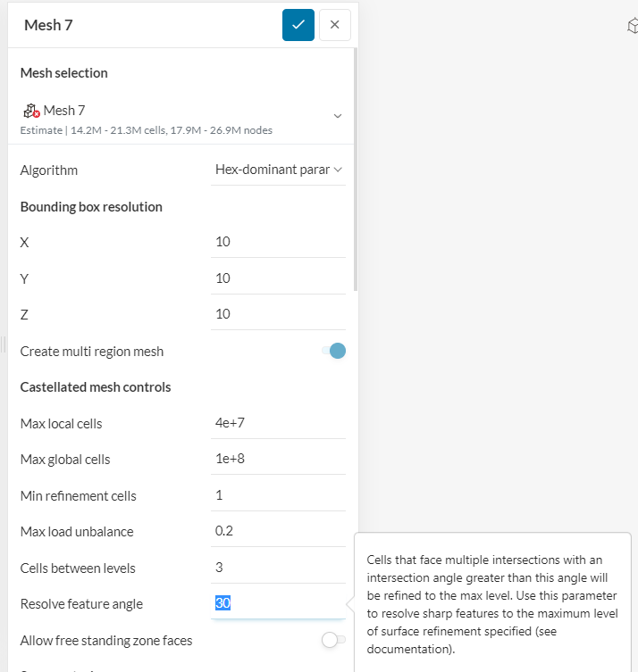
If this is not desired, I’d suggest removing the feature refinement.
- Now, on the standard vs hex meshes topic: the CAD model is not clean (we have a huge number of small faces), so I would not encourage you to use the standard tool. This is a long topic, but in short the standard meshing tool is bottom-up (surfaces are meshed first) and hex meshing tools are top-down (volume is meshed first, and then the surfaces).
For this reason, the standard tool can capture surfaces much more accurately than hex meshes. However, this is a problem for your geometry, because the surface topology is not clean. Then we have very poor cells being generated on the surface, and everything goes bad from there.
Of course, the other alternative would be to clean up the model a little more, and then you would be able to use the standard tool.
If you’re interested in more info, searching for top-down and bottom-up meshing strategies should be an interesting read.
Cheers
@Ricardopg Many thanks for this! Making the changes you have suggested.
I understand the rationale behind the two meshing alg. and yes like you mentioned, a higher concentration of nodes were present in the grid where there were the smallest faces on CAD using the standard mesher. Will read through the docs to get a better understanding. What would be the procedure you would recommend in terms of cleaning up the CAD, getting rid of small surfaces?