Im currently running different simulations and either im just a genius or, im doing something wrong.
im trying to apply 4,000lbs( MIN) of force to a ramp and the results were great i think. i really do not know what im looking at to be completly truthfull. so then i did 16,000lbs and the results are very similar.
maybe i could get someone to help me out and look it over?
Jokes aside, your setup looks basically ok, besides some details regarding the contacts. Looking at this project: SimScale
Just two things that definitely need attention:
you applied a geometry operation to scale your model down by a factor of 0.001 and now it’s about 0.5mm large. Is this correct? you apply an extremely high force to such a small model, resulting in nonphysical stresses of ~1e7 MPa.
you completely fix the steel part - this is probably fine as you don’t expect much deformation there compared to the aluminum part, but maybe you should check if you can actually neglect the deformation there by only fix the two end faces (or whatever makes sense for this application).
Maybe you could help us a little better understand the application, this would make it easier to come up with improvement suggestions.
@jousefm I successfully completed a simulation, could you possibly look it over and tell me if i did it right?
if the pictures above are still not enough i can explain in better detail. thanks again!
and apologize for needing so much help Iv just never done anything like this.
Sure I will have a look at it later on. Did you expect any value or a specific range for the stresses? The application you are doing the analysis for is a hydraulic ramp. So what we could do first is a static analysis (as you have already done) where we check the von Mises stresses in order to check if the structure fails under the given load and in addition to that investigate fatigue under static and cyclic loading. @BenLewis is very experienced in those applications and has given some good input on how to extract cyclic stresses from the results which would also apply for your application. For instance when the ramp stops you have something like a damped sinusoidal load acting on your structure that could be investigated.
And no worries about asking, that’s why we have the project support section
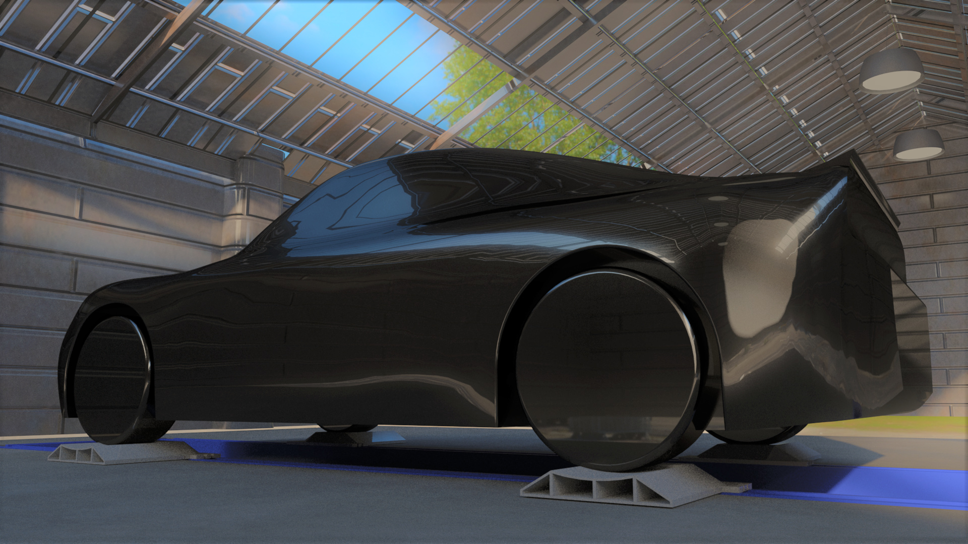
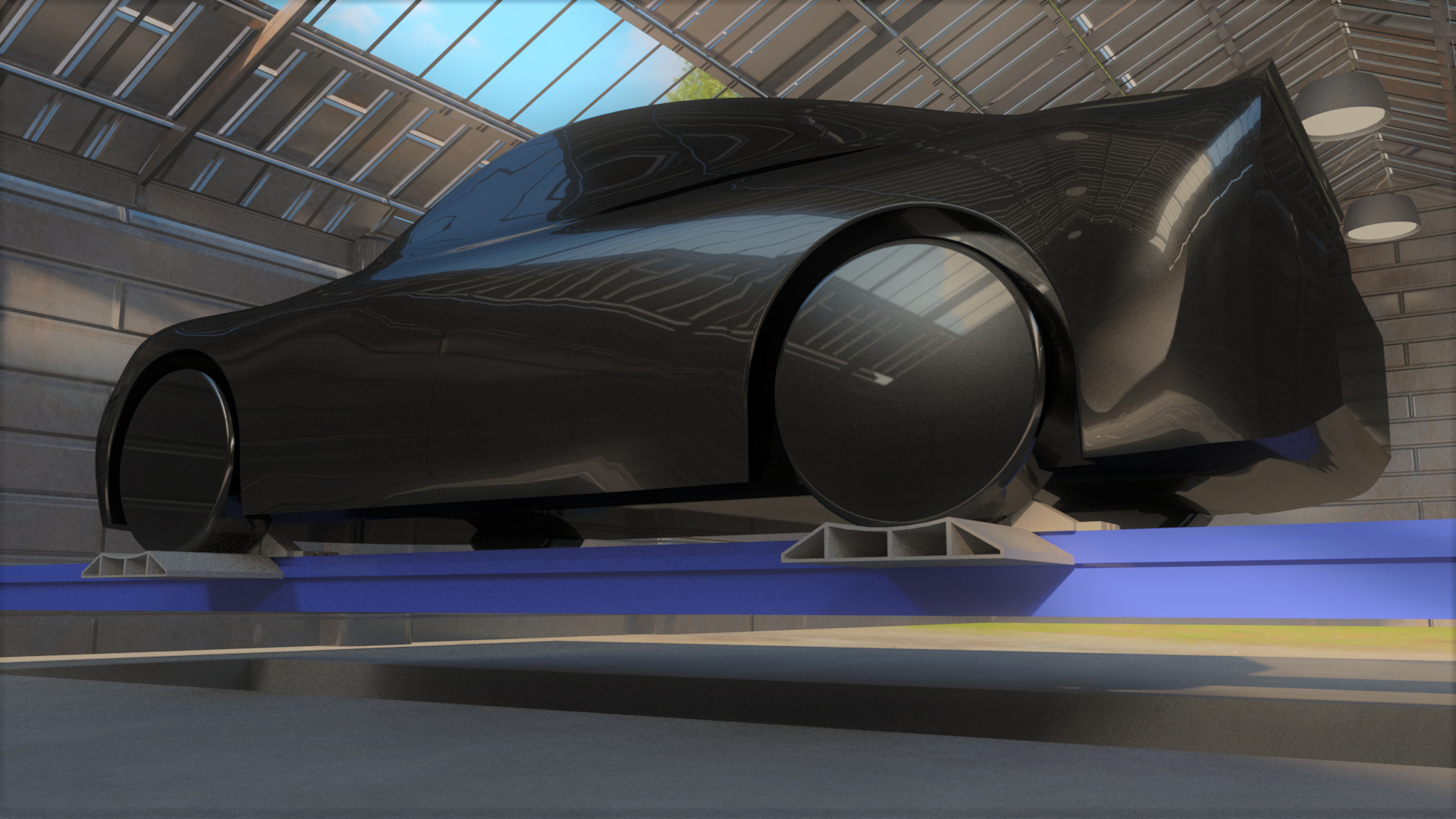
the current process of loading a car on the machine is very time consuming! you have to lift the car with the machine and then stick those blue tire stands under each wheel and then lower the machine back down to separate the car from the machine and then put the clamps under the frame and then raise the clamps back up to the car to secure it to the machine in order to make your repair.
the problem with the machine is that i can not put just a fixed plank stile ramp due to the angle of the scissor arms that lift the machine. when the machine is all the way down the arms are almost parallel with the ground so the hydraulic cylinder that lifts the machine is pushing horizontally instead of vertically.
so the ramp i made allows the machine to start its lifting process with no downward force just enough so that the hydraulic ram is pushing in a vertical direction. so the ramp is stationary on the ground until the machine reaches the proper height and then it locks in (no hydraulics involved with the ramp itself) here is a link to a render video of its simple function. https://youtu.be/voGu1_6M8Jk
Hi! Just wanted to share some thoughts on your project:
First of all: nice idea, hope it works!
I see you have modeled the multibody assembly. If what you want to do is to assess the resistance of the parts, then I suggest to analyse each part separately. Start with the part that receives the tyre, fixing the support faces. Then translate the reactions as loads to the next part. In this way you will get simpler analysis (remember, divide and conquer).
If later you would like to simulate the lift/clamping behavior, then the multibody model is necessary. This is a more advanced simulation as you would have to apply physical contacts and time dependent boundary conditions. But don’t worry, it can be done.
Always start simple, then approach to the more realistic model by adding complexity in steps.
PD: By the way, 4000 lb are 1800 kg so 18 kN (give or take). I see you have 71 kN, and in three points, so 213 kN total, that’s a lot for this small part! Also, I think it would be more realistic to apply a face load where the tyre would rest.
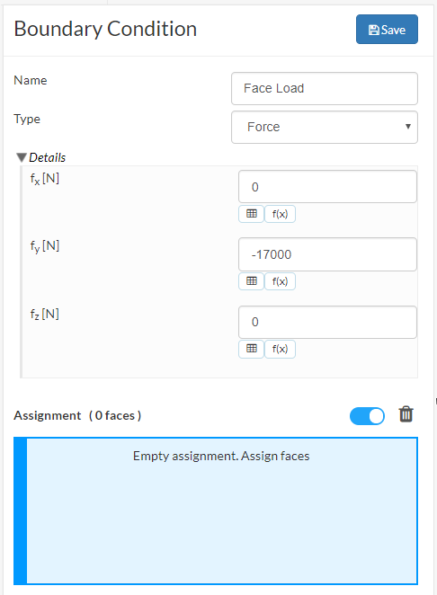
Thanks so much that makes a lot of sense! So if i do a surface load the formula is different, its [N/m2] instead of [N] how do i convert 17651.97[N] to [N/m2]?
Actually what you want is the load type called “Force”. There you define the total vector force and select the faces where it will be applied, then the solver will take care of the area distribution. Read the documentation for more detail.
how do i know if the results are good? do i need to do something so y’all can see it? or are the results visible, i just need to know well the ramp hold the 17 kN safely.