Greeting
I looking at testing a Trombe wall integrated in a wall system.
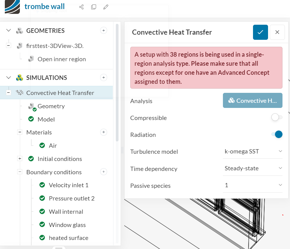
I don’t fully understand how the flow region works and I this error message.
A setup with 38 regions is being used in a single-region analysis type. Please make sure that all regions except for one have an Advanced Concept assigned to them
Here attached is the project:
Please could help me, please
Thanks in advance.
Hi,
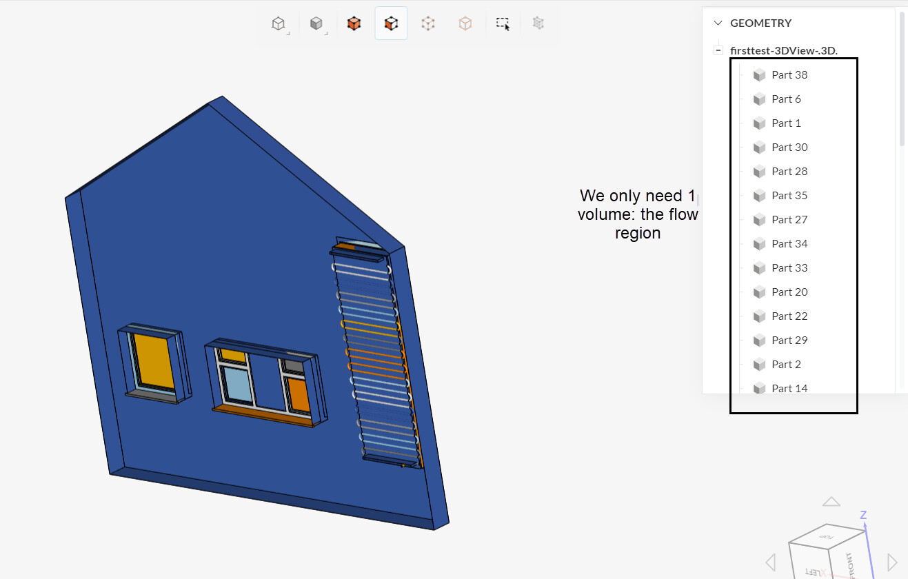
For all CFD simulations, since we are interested in calculating the results on the flow region, it’s necessary to create the fluid volume for our geometry.
This can be done directly in your CAD software, or within SimScale with a flow volume extraction operation (see the doc page here).
Additionaly, the only analysis type which allows to keep the solid parts is conjugate heat transfer. For all other analysis types, only the flow region should be in the geometry (other than eventual advanced concepts volumes like power sources and porous media).
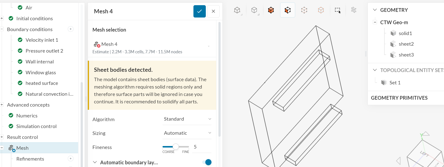
By keeping the solid walls, you are going to run into that error message, when using a convective heat transfer simulation:
With that being said, when running the flow volume extraction in SimScale, make sure that the “Keep existing parts” option is disabled (fig 5 in this article).
Cheers
1 Like
Hello @Ricardopg
Thank you for your answer, I have tried this tutorial
I probably need to edit the CAD I will give it a try, If i well understood I need to select the faces that enclose the zone where air Flow and everything outside should not be in the geometry.
Thanks
1 Like
Hi!
The workflow depends on where you are intending to create the flow region. For your application, the typical operations would be open and closed inner region operations.
As the name suggests, open inner regions would be used when we have openings in the model, whereas closed inner region operations would be used when the model is fully closed.
But you are correct - the geometry should have a single volume, representing the flow region. The other volumes, representing the solid parts, should be deleted, or you are going to run into multi-region mesh errors.
This article provides more details on the topic!
Cheers
hey @Ricardopg
Thanks for your reply, I have no clue on how to assign as solid parts or flow region?
I tried to create very simple cad here but I still can’t create the opened close region.
Thanks in advance
Hi,
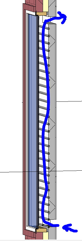
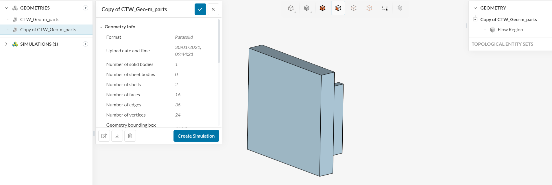
Are you trying to create a flow region internal to this volume that you linked? If that is the case, the volume already consists of the flow region.
If you inspect it in your CAD tool, you will see that it is fully solid:
If you create the flow region in your CAD tool, there is no need to run an additional flow volume extraction operation in SimScale.
Cheers
No I was just trying a simpler Geometry. I don’t understand how to assign a single volume for the flow region and assign the other to what can be useful too.
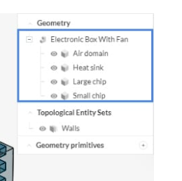
How do I get to geometry tidy like it is on this picture from one of the tutorial?
And also there is problems with the mesh here because of the sheet here I deleted them in the CAD edit but the geometry is no longer visible.
I cannot find any tutorial how create a CAD geometry that works for simscale.
@Ricardopg , could you help me understand this part, please?
Hi,
Some comments based on your questions:
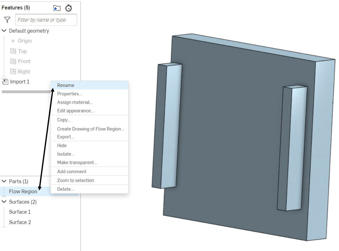
- It’s possible to name the parts in your CAD tool. On Onshape, for example, it would work like this:
The same name will be displayed in SimScale.
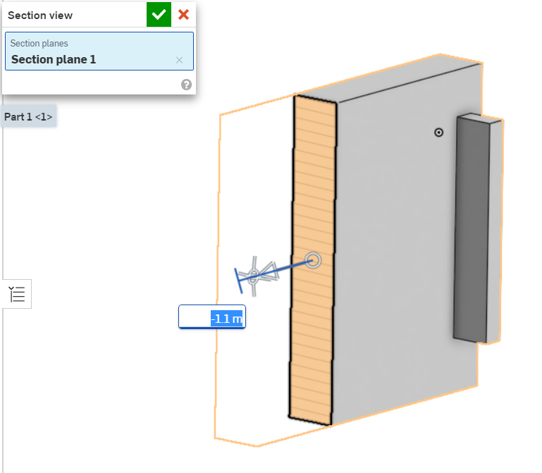
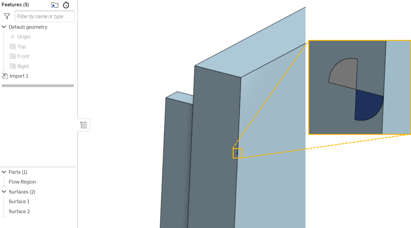
- If you try to hide the “solid1” volume, you will notice that there are 2 sheet faces next to the origin (0, 0, 0). Note that sheet parts are not desired for CFD/FEA simulations.
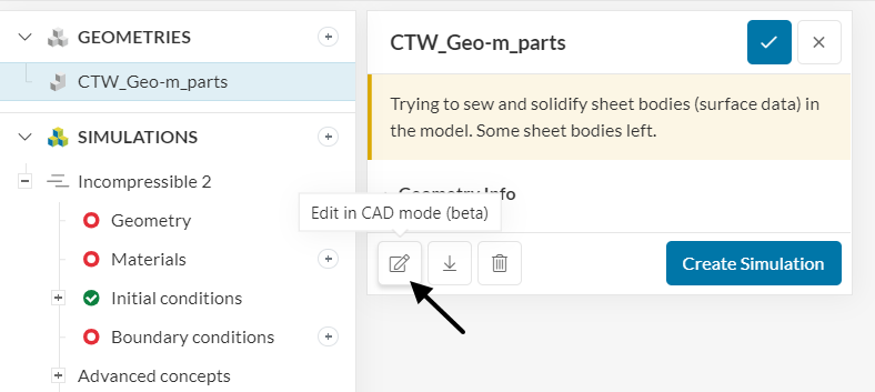
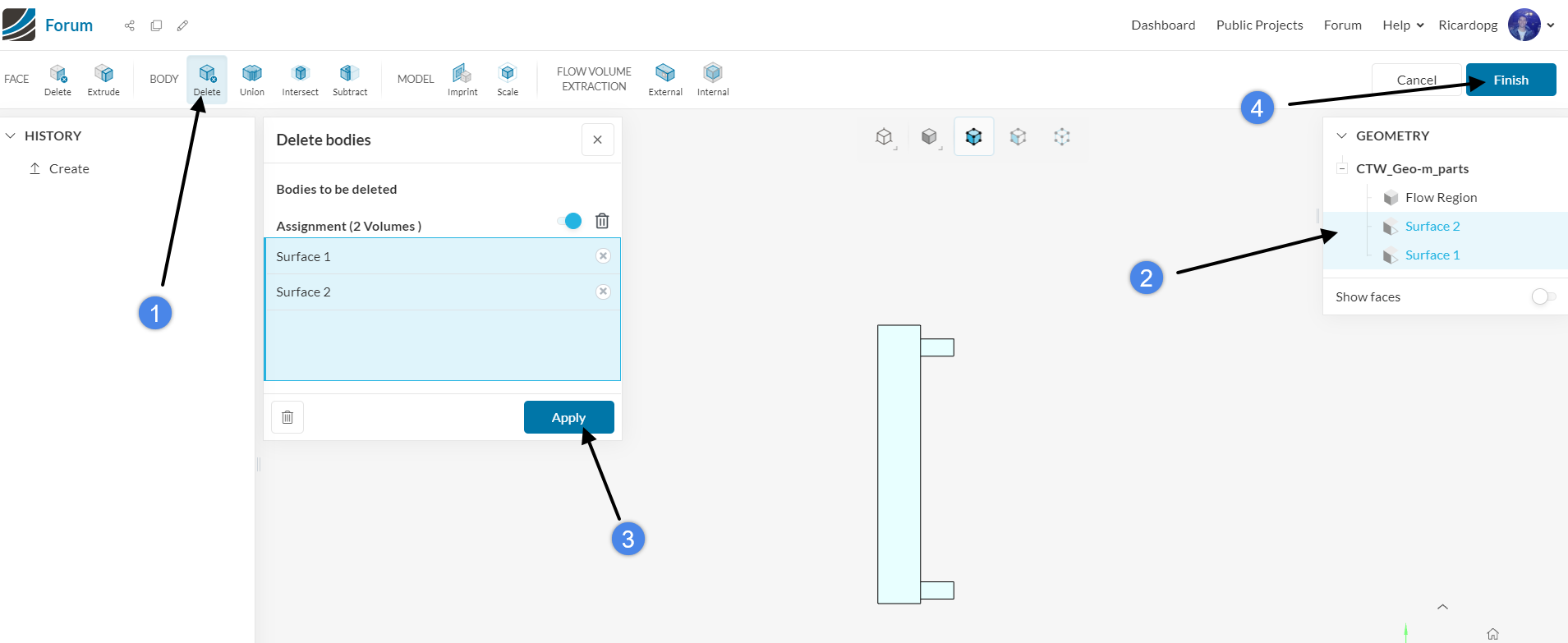
These are the two sheet parts that are reported in your images. In any case, you should be able to delete the two problematic faces using the newly released CAD mode:
These would be the steps:
As a result, you will receive a clean geometry:
Hope this helps 
Hey @Ricardopg
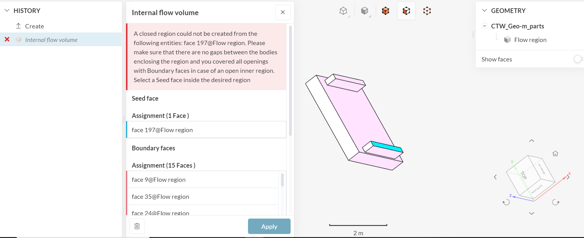
Thanks for that but none of it worked I tried those above from the CAD beta and also from onShape. but it does not work here the message I got.
I have tried also to assign ian internal flow volume maybe the error my help you understand what is going on.
Hi,
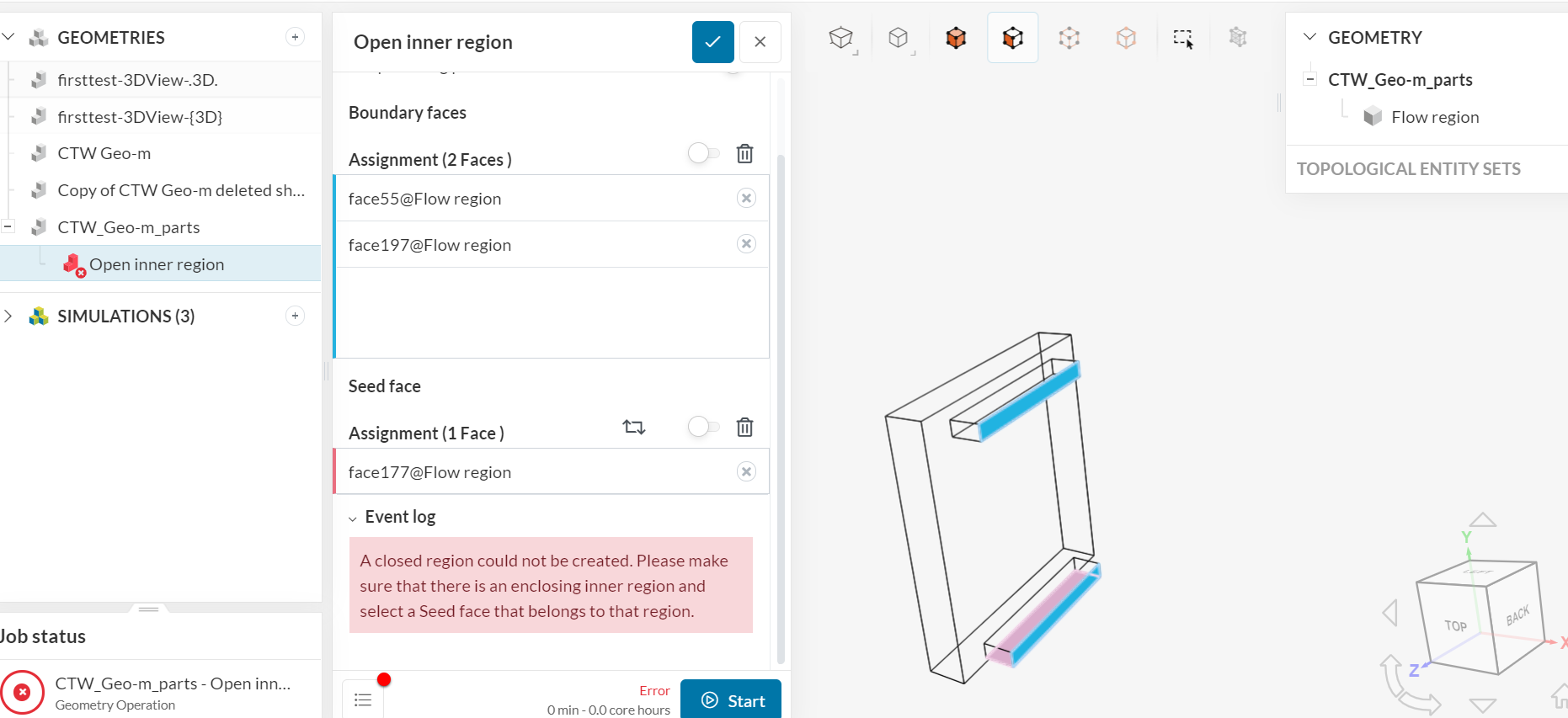
Could you please review the post #6?
As I mentioned, the current volume that you are working with is already fully solid (it already consists of a flow region). Therefore, attempting to run an open inner region operation on it will always fail.
Just to clarify, if the model already consists of a flow region (i.e. it’s already fully solid), then there is no reason to generate a flow volume again in SimScale.
Cheers
Hey
Thanks a lot.
The simulation worked this without inner region. but so if I if model more than on volumes then the inner region tool will work I suppose.
The flow volume extraction operations should only be used if there is a “void” in your domain. With the flow volume extraction operation, you will be able to create one volume that will fill this empty space.
Cheers