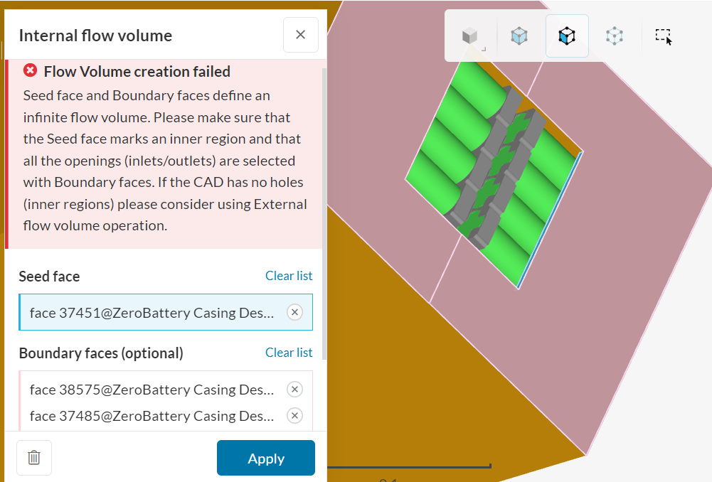
I am new to SimScale and have no previous knowledge of CFD, but I’m trying to use it for my university project. I am trying to model the effect that air flow has on the temperatures of the battery pack, but I am unable to create the internal flow volume prior to running the simulation.
There are gaps that exist in the battery pack but it was designed to be this way and I am not sure how I can resolve this issue to create an accurate simulation. Simply running the simulation will generate these errors below that I have no idea what it means.
Can you share a link to your project here in the forum, so that we can have a look at it?
In regards to the general setup of the simulation, I’d suggest having a look at this tutorial.
Hi ww680
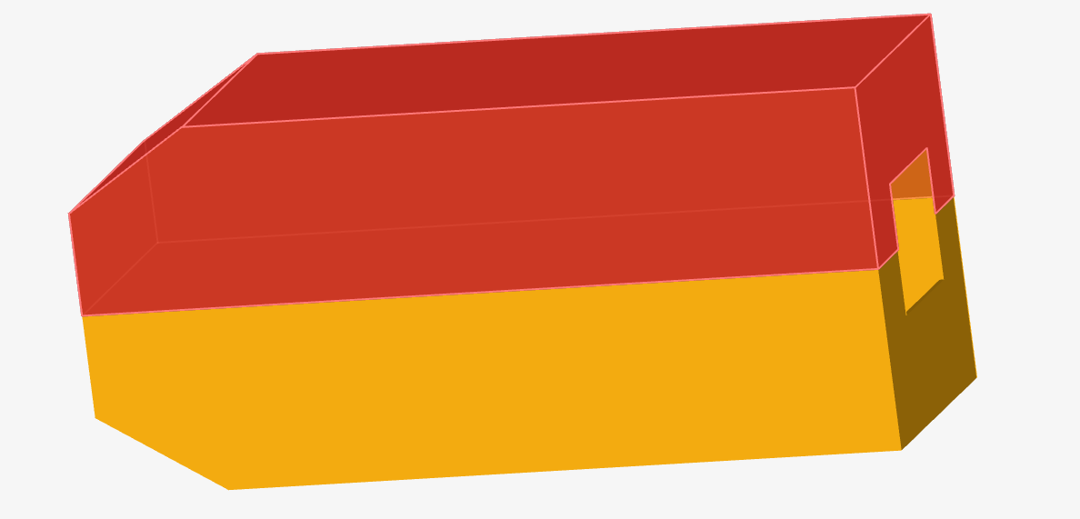
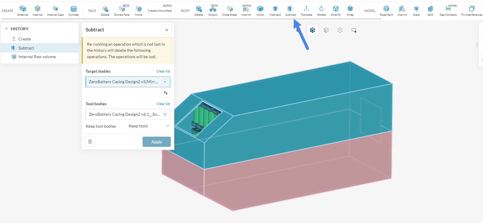
I was able to create the flow volume. the issue is that the top and bottom parts of the housing are overlapping.
therefore please use the subtract notion, and subtract the top from the bottom part.
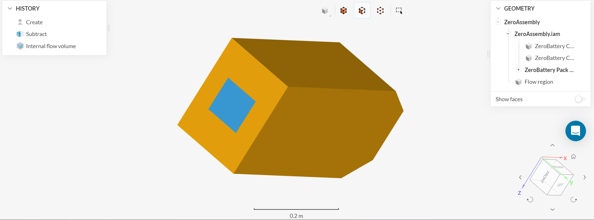
then you are able to create the internal flow volume, using the boundary faces you have selected.
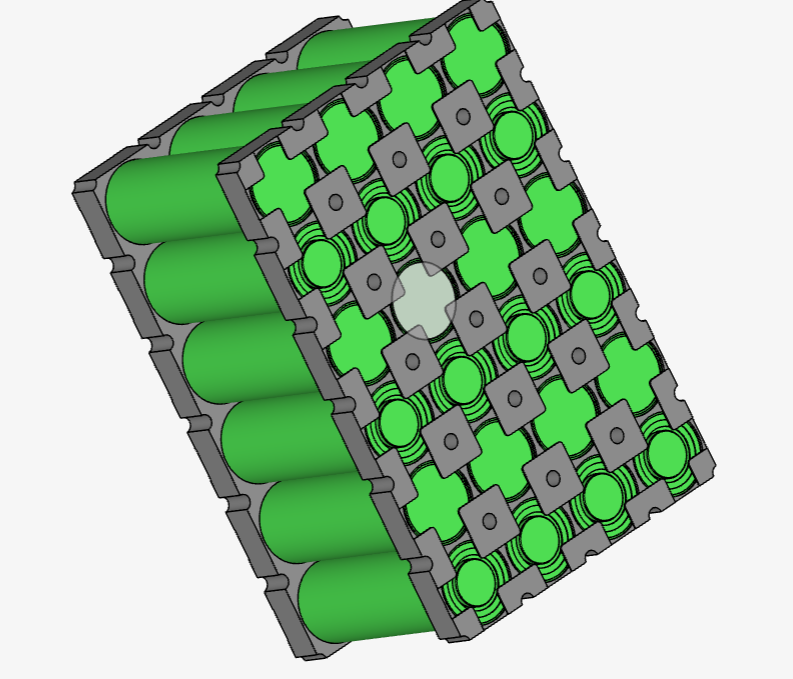
On a further note, I would recommend reducing the level of detail from the battery stacks.
I would recommend to defeaturing the stacks, as these details will get captured by the Mesher, and will require a lot of cells, in order to be captured accurately.
this will cost a lot of cells making your simulation take very long to run or will cause the simulation to diverge if the details are not captured correctly.
can you please share a link to the project where you were able to create the flow region? Also when done please ensure that you have exported the new CAD file with the created flow volume, and set up the simulation again with the exported CAD, that contains the flow region.
For the simulation setup, you can have a look at the tutorial above, which should provide good guidance on how to set up this simulation.
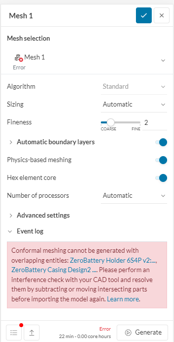
I have followed the tutorial by applying things that would fit my own battery pack but when it comes to running the simulation I get this error occuring:
My issue is that running the interference check usually takes an abnormally long amount of time and it never seems to complete. This means that I am unable to resolve the intersecting parts.
The link to my project:
If I can have some guidance to how I can manually subtract these intersecting parts to make the simulation run then that will be great, thank you. Also, is there any way to reduce the time to simulate as it is taking a very long time?
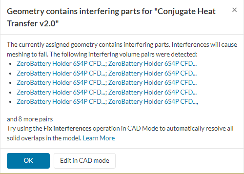
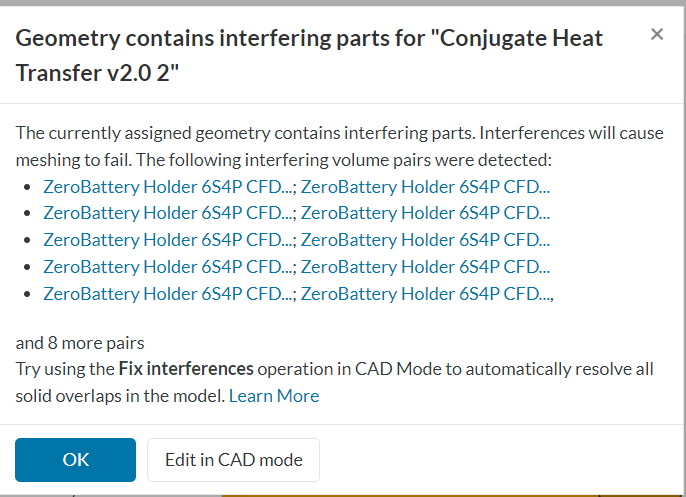
I have made a new version with the simplified cylindrical batteries and have also removed the clamp holes at the top, but I am still getting interference errors and I cannot resolve them through “Fix interferences” since it would just end up processing for hours and not change or allow me to exit it.
Is there any solution to this problem as I really need to get this simulation running as soon as possible to get results for my project.
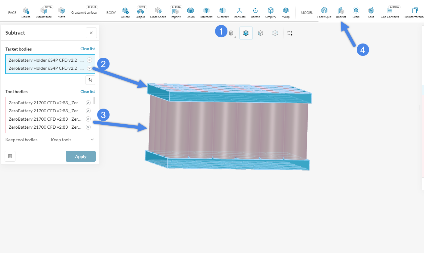
you can use the subtract option in the edit in CAD Mode in order to fix these interference issues.
Please do this for all cell stacks, before creating the internal flow volume.
Select the Subtract option
Use the holders as target bodies
Us all Cells as tool bodies.
Once you are done with all Stacks (you can also do multiple in one operation) and the internal flow volume is done us the imprint option in order to ensure that your contacts are good.
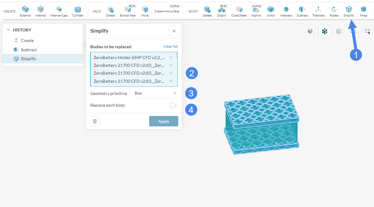
Another more simplified option would be replacing the cell stacks with blocks, neglecting the flow around each cell.
this would then result in the general flow through the cell container and will cost much less computational effort.
Once enough understanding is done here, you can try again by doing a single-cell stack trying to understand the flow through a stack.
You can do this by using the simplify option in the Edit in CAD Mode:
Yes, I have exported my imprinted geometry with the flow region previously. You can try doing the same and you’ll see the errors pop up still. The new one should be named as copy of the original battery right?
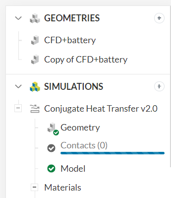
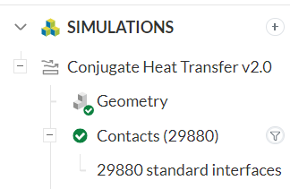
Also, after having setup everything else, the number of contacts is still refusing to load on the flow region export. The number of contacts will only load if I create a conjugate heat transfer on the original battery pack that has not undergone any changed under CAD mode but then this will result in partial interfaces. So do I simply wait or is there another solution for this?
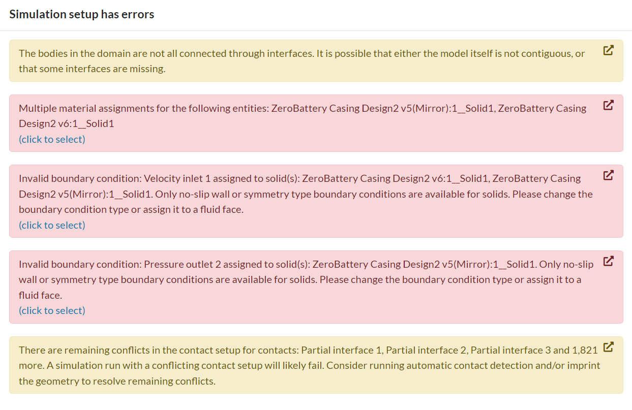
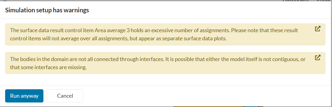
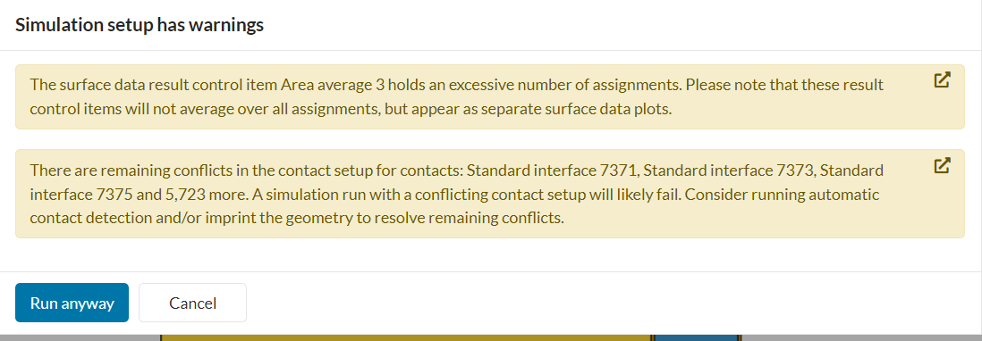
This warning pops up when I try to run the simulation when the contacts have no loaded yet:
I believe the Area average 3 resulted as I am trying to see the temperatures across the surface of all 456 battery cells but I don’t understand the bodies in the domain not being all connected through interfaces (possibly due to contacts not loading yet?).
I have created 3 different iterations to try and get the simulation to run but I cannot do it no matter what and I can’t fix it, I’m not even sure how these interferences are occuring and why I cannot get rid of it with subtract tools or imprinting.
Here’s the link:
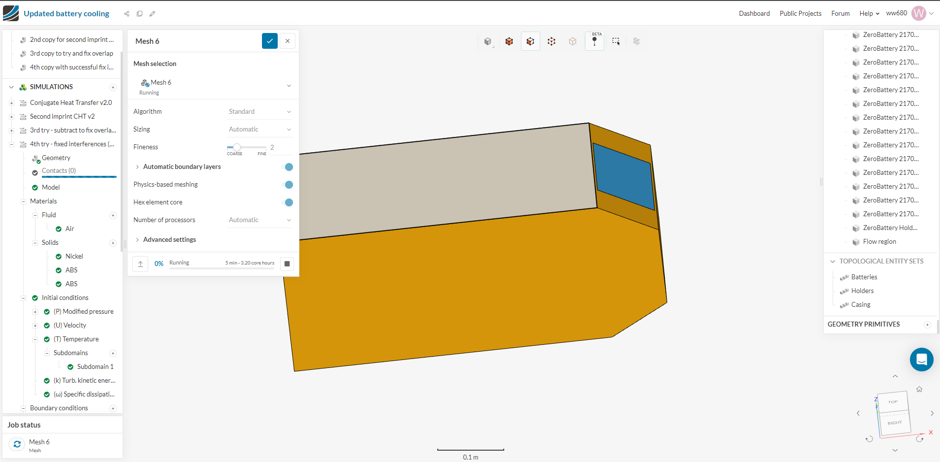
Update: With the fourth iteration I ran fix interferences and it gave a pop-up with interferences being fixed. I will try running the simulation now to see what happens…
Also can you possibly verify if my simulation is setup appropriately to run or if anything could be missing? I just want to show the air flowing through the inlet out of the outlet and how the temperatures across the battery cells will be affected by this.