Hi
I have been trying perform a Incompressible flow simulation on a helicopter, now when I try to select the Closed cylinder as the rotating zone, the whole mesh region is now selected and assignments are directly being assigned to the mesh so no other region is available thought of enabling the multi region mesh option but again my project isn’t related to CHT simulation so didn’t enable that one.
The link of the project is below
This issue has already been reported by our PowerUser Andrzej (@Retsam) here: MRF zone not meshed when making mesh copy where MRF is OK. The engineers are currently looking into this - once this has been resolved we will inform all of you! Very sorry about the lost productivity and time so far.
In your case the refinement is not high enough and you can see the both MRFs being merged which is not very benefitial. I am also thinking that the height difference between MRF top and top BC is a bit too low and also the diameter of the MRFs which might influence the meshing of the blades and result in unphysical results. The “Allow free standing zone faces” option is off in your case so I would just try it with higher refinements.
Edit: I also think that your region is open somewhere which causes the mesh to fail. Have you checked for watertightness beforehand? @anirudh2821998, @Retsam, @Get_Barried & @DaleKramer, any other input from your side?
Currently, you ill-defined your future MRF zones: You need two zone, first for main propeller, second for rear propeller.
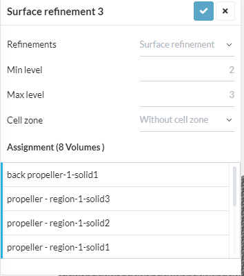
Call those surface refinement zones (without cell zones) “RotZoneMain” and “RotZoneRear” as an example. Then you need to assign only ONE cylinder for each of them. DO NOT PUT IN what they contain in your geometry.
So your RotZoneMain will contain ONLY Propeller-region-1-solid4 and your RotZoneRear will contain ONLY Back propeller - region-1 - solid1.
Actually you need to carefully define also surfaces to refine (but this time do not use ‘without cell zone’ option), as parts which rotates would need better surface mesh compared to body of helicopter.
For “region refinement” do not use the whole Background Mesh Box (BMB): play with Geometry primitives and add just necessary box size for your copter. Without that you will be consuming core-hour for mesh which is too fine in remote regions. @jousefm mentioned already that your BMB ‘ceiling’ is not high enough.
Anyway you need to experiment with meshing, use Mesh Clip once mesh is generated to see fine details of your mesh.
Try reducing the number of component by either combining them into single body or removing the irrelevant part that don’t interact with the fluid. This will easy the process of defining B.C. and MRFzone.
Also, if I am not wrong then the “with cell zone” feature should be selected in order to make a different cell zone for the rotating region.