\underline{\textbf{Status}}
Not started yet.
\underline{\textbf{Description & Overview}}
Information: The CAD models will not be provided and have to be modeled!
Heating, Ventilation, and Air-conditioning (HVAC) systems in buildings and other enclosed spaces are crucial for creating a comfortable and healthy indoor environment. These HVAC systems always require duct systems to deliver air. To increase the energy efficiency of the fans in HVAC systems, the pressure loss of the duct network should be minimized, which would require accurate estimation of the pressure loss coefficient of the duct fittings.
Knowing loss coefficients of duct fittings is crucial for designing a duct network for HVAC systems. Traditionally, the coefficients have been obtained using experimental measurements according to AHSRAE Standard 120, a process which is time consuming and expensive. An alternative is to use CFD, but this has uncertainty due to the approximations used in modeling turbulence. This study first validated three turbulence models by comparing the predicted loss coefficient of an elbow with the corresponding experimental data from the literature. The Standard k-ε model and Reynolds stress model could accurately predict the loss coefficient; however, the more advanced LES model failed. The study found that the surface roughness of the straight duct connected to the elbow had a significant influence on the predicted pressure loss and that the accurate surface roughness could be determined. Then, this study applied the same procedure and turbulence models to predict the pressure loss coefficient of a lateral and a tee junction with both converging and diverging flows. The results show again that the surface roughness of the straight duct connected to the junctions was very important and that the best value could be estimated. The pressure loss coefficients predicted were accurate when compared with the experimental data available to us after the simulations. Some discrepancies between the calculated and measured results exist that could be attributed to the approximations used in the simulations or the errors in the experimental measurements.
\underline{\textbf{Input Data}}
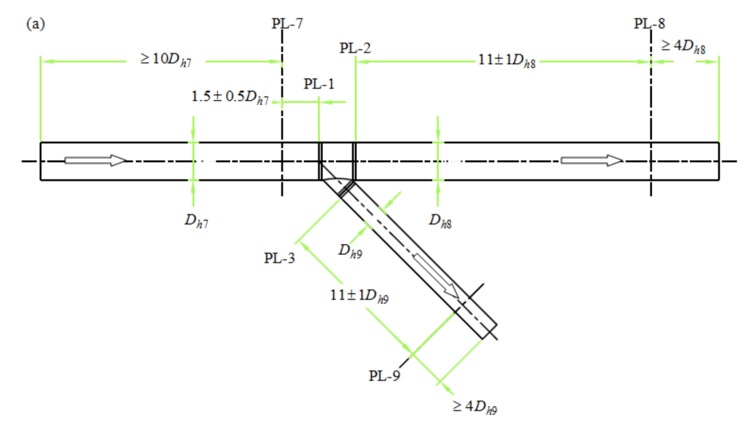
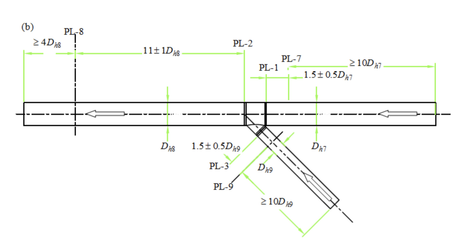
Fig.1 (a) Diverging and (b) converging airflow test apparatus used by ASHRAE Standard 120
The following important dimensions are in the paper:
-
Geometry of the duct fittings
-
Inlet velocity and flow rate ratios for the four cases
-
Conditions for testing different surface roughnesses of the straight ducts
-
The optimal surface roughness of the straight duct and turbulence model identified for the four cases specified by ASHRAE RP-1493
\underline{\textbf{Purpose}}
The existing design guides for duct systems do not include many of the duct fittings used in HVAC systems. This compels designers to make intelligent guesses for some of the pressure loss coefficients used in their calculations (Shao et al. 1995). ASHRAE Standard 120 provides a standard experimental method of testing to determine the flow resistance of HVAC ducts and fittings. Kulkarni et al. (2009) measured the pressure loss coefficients of flat oval elbows with various aspect ratios. The experimental measurements could be accurate, but they are expensive and time-consuming. SimScale will be used to validate the results given in the paper (source below).
\underline{\textbf{Pictures of some results}}
All the results can be extracted from the paper.
\underline{\textbf{Key Words}}
Computational fluid dynamics, CFD, HVAC, Mathematical models, ASHRAE, American Society of Heating, Refrigerating and Air-Conditioning Engineers, Pressure Loss Coefficient, AHSRAE Standard 120, Heating, Ventilation, Air-conditioning
\underline{\textbf{Literature & Sources}}
\underline{\textbf{Helpful Sources}}