I just stopped it when both CD and CL were 1% stable over 500 iterations with a 50 iteration moving average 
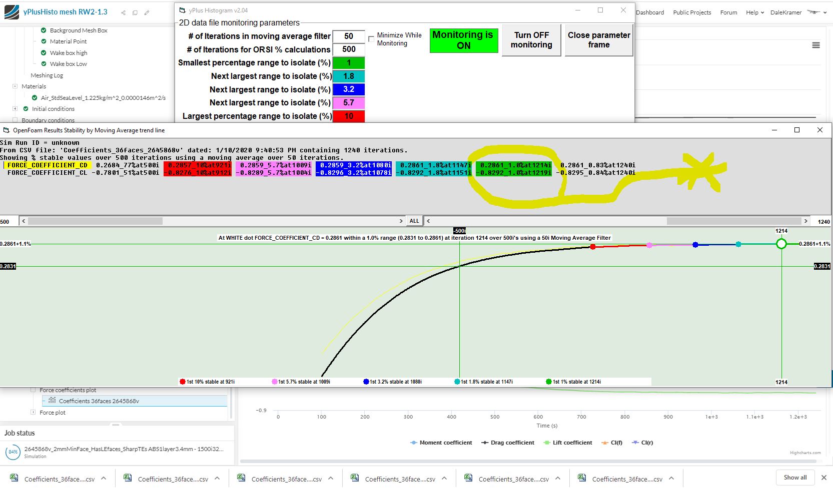
I like it when a plan works…
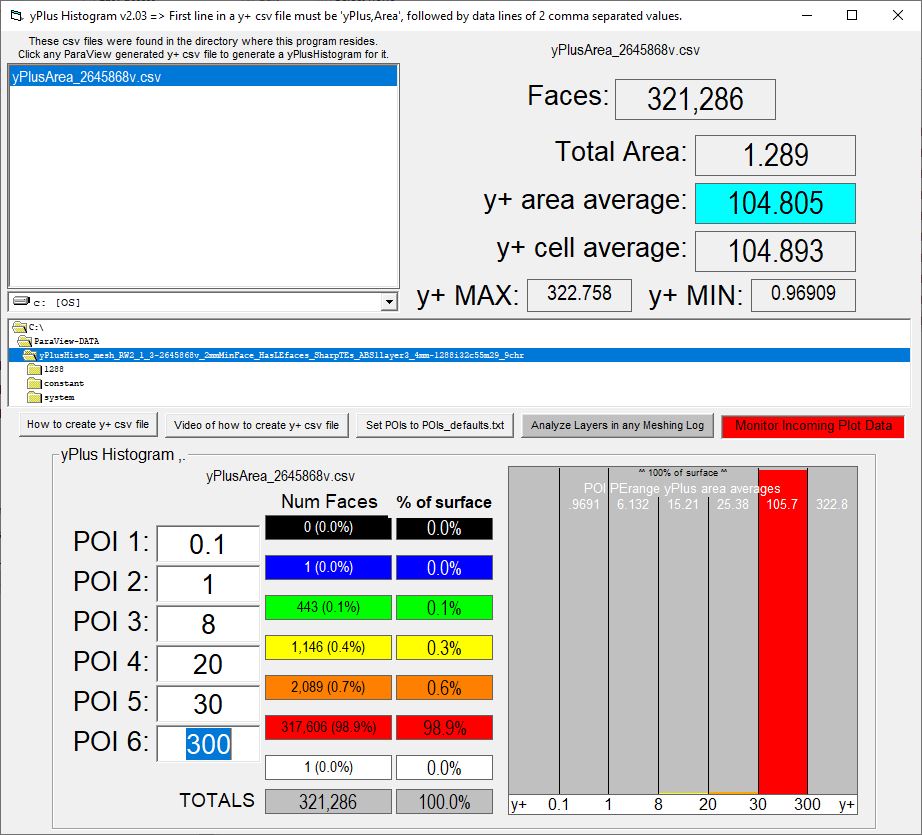
I doubled your 1st Layer thickness and now we only have 0.4% of surface area with yPlus < 20 


1 Like
Ok going in order
- I agree geometry is very important. The connection between correct geometry and mesh quality/no problems is very strong
I agree sharp TEs are better then 1-2mm TEs, I will change this on all wings
Edit sorry i keep forgetting that i cannot assign a region assignment to faces, this is really a feature i would like to have. Forget all that is written below
Here is where i have a problem. I see you split the face, but did not assign a higher level. Keeping the leading edge faces at level 9 (because the region refinement wont allow for switching these to level 10) seems like a waste of work. There is no change. The only reason i wanted to split the leading edge face is so that i could apply a level 10 region refinement and surface refinement to this area. This would increase surface mesh quality, especially for the smaller radius of the element leading edges.
This is great work! im fine with having one layer and that it is bigger the the region/surface refinement if it means almost all Y+ values are between 30 and 300!
Do i have to download your ORSI program as well? can you send me a link?
Will do sir!
I was only doing this because the FSAE tutorial said to
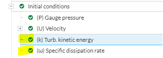
I was looking at changing K and omega here. i didnt know you could do this right in the velocity inlet… what is the difference?
I will start using slip walls instead of symmetry
When you mean stop the sim i assume you mean here? Just hit cancel when i reach the 1% and under stability of Cd and Cl

P.S. I have copied your split LE project and made a new trial HERE I have tried to change just the elements to level 10 along with the region refinement. This should help with element leading edge quality as the element have the smallest LE radius.
I had to leave something for you to do ![]()
Yes, when I monitor manually a sim run with ORSI plots, I set the ‘Write interval’ and ‘End time’ to LARGE values (usually 5000), in this test I used 1500 since I wasn’t sure I would be around at the end…
I am not sure what the difference is but I prefer to use the custom inlet, it is more flexible.
ORSI plot monitoring is in my yPlusHistogram v204, just put a copy of the exe in your browser downloads directory where it will scan that directory every second (when Monitoring is ON) for new CSV plot files that you download from SimScale. Turn monitoring ON, on the form that appears when you click the RED button… I haven’t put those (or any) instructions on the feature in the program or ReadMe file yet, that is on my ToDo list ![]()
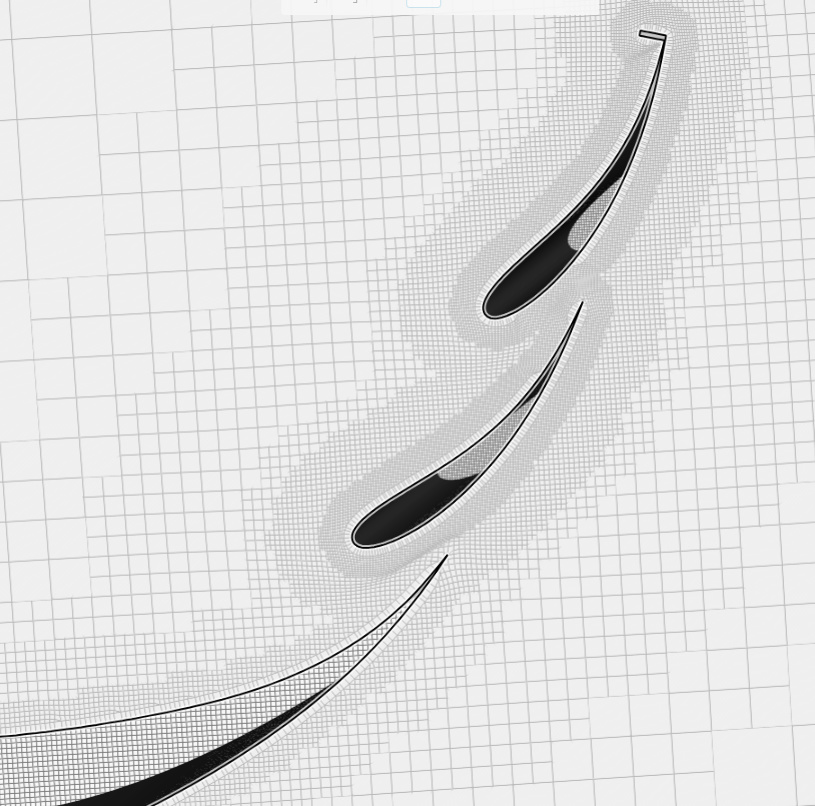
Lately I have been struggling with issues similar to you when I try to layer the treads on my CyberTruck tires to a y+>20…
You have the same issue between your wings…
Using 1 layer solves the yPlus issue but leaves doubt if the turbulent BL is fully analyzed in thickness. We have small hex cells close to first layer and the solvers have good resolution there if we have not captured all the turbulent thickness.
Fortunately I believe that the k-w SST turbulence model does still evaluate wall function in Hex cells, so I am hoping we are OK.
My CyberTruck mesh looks good but I have not been able to converge a run with 1 layer on the tire treads. It is timely that your 1 layer meshes’ sim run converges well.
I think you should make a CAD file without the middle wing, make a mesh for a ‘standard’ 3 layer with 1.3ER at 3.4mm 1st layer AND a mesh with a single 3.4mm layer… Then run a fully converged sim run on each… Then we can evaluate the results difference… I suspect there will be very little difference…
Are you up for that ![]()
OK, now I will come full circle to this…
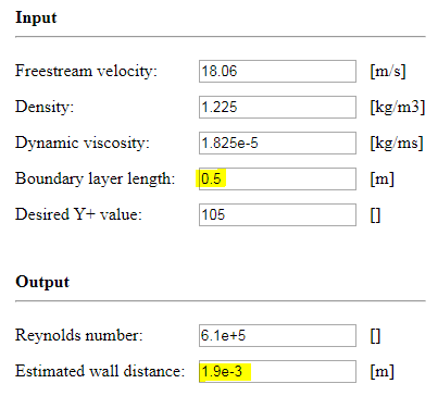
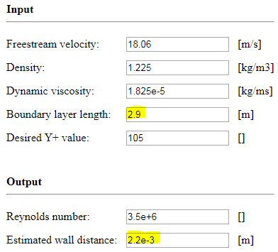
Now that we have yPlus average at 105, lets put things into the calculator for that:
.
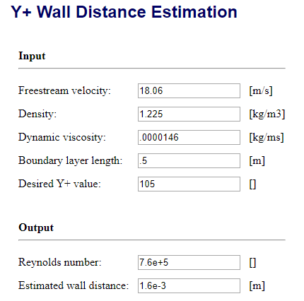
Since this is a calculator that shows centroid distance as ‘Estimated Wall Thickness’, we need to double its output of 1.6mm to get 3.2mm 1st layer thickness… That is pretty close to the 3.4mm 1st layer that got us to yPlus area average of 105 ![]()
![]()
![]()
![]()
Thanks for the ORSI info!
yes im up for that, the least i can do when you have helped me so much !
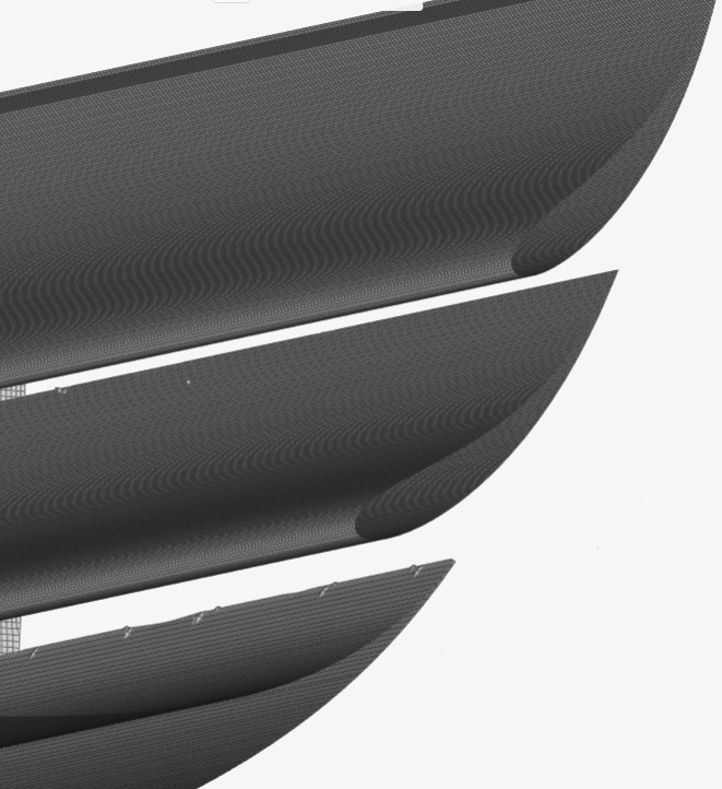
Here are the results, although i dont think this will be do - able because a half wing mesh is already at 6.6 million cells. I still have a whole car to mesh haha
Also deleted layers here for some reason
Main wing TE has some bad cells … not sure why
I am using different values for dynamic viscosity and boundary layer length. Any reason you are using 0.5 m for length? is it because this is the width of the rear wing? I am still using 2.9m even though its a stand alone model because eventually it will be based on the whole model length. Or do you suggest to use the actual wing sizing because there will be multiple boundary layer refinements anyways?
The Y+ changes quite a bit based on reference length
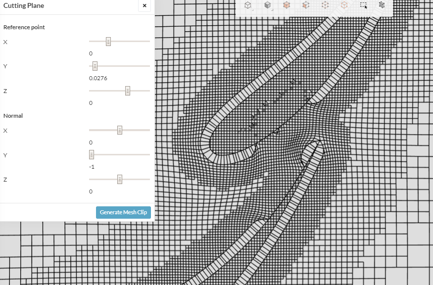
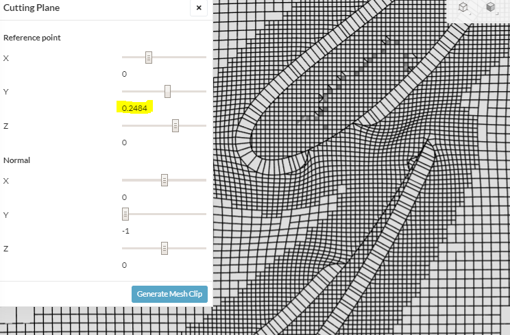
Is that at y=0, if so try meshclip at y about 0.25…
I think with some effort you can reduce that to a couple million range, you have the tools…
Yep, I still get bumps on my tire treads, I am working on that. Try feature refinement maybe. Sharp TEs are difficult sometimes. Those single cell glitches probably are not deal breakers tho…
I used the approximate length of your endplates (I think normally for cars you use length of vehicle, but here all geometry is max 0.5m, who knows what length the solvers use when they generate the yPlus values (I have not figured that out yet). I would like to assume my assumption matches what the solvers use since the results match so well…
I use the values for STD atmosphere at sea level, I have not figured where on earth the air matches the defaults in SimScale ![]()
Nope still there
I think when i mesh the whole car and have cells to spare. This is where i will increase the level first
Try 0.25 not 0.025…
I think it is time for a step backwards, try again with distance ref and ‘wake box high’ with no assigned faces/primitive… Perhaps set cells between levels lower too???
Once you get full coverage, then add more refinements as needed, trying to keep full coverage…
EDIT: also shouldn’t need such small cells just outside prism layer…
yea i noticed that both my wake boxes arent meshing. I originally though this was because of the lower levels in the distance to geometry refinement. Not sure. I will come back to this after i complete the sims you asked for
Must be private project…
Darn it, sorry, forgot about that flap on rear wing, what is its purpose 
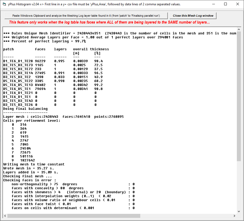
I think we need two meshes that are about equal layering percentage for a valid test…
The 3 layer is only 92.5% while the 1 layer is 99.7%:
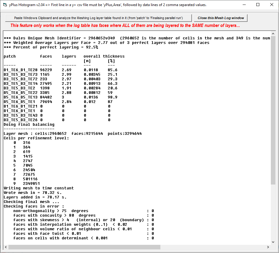
.
I think we need to take that rear wing out of CAD too, what you think
i assume your goal with this test is to compare the 3 layer BL and 1 layer BL in how well they cover Y+ surface area. I understand your concern that a 1 layer BL wont be able to measure the turbulent region that starts above the BL total thickness.
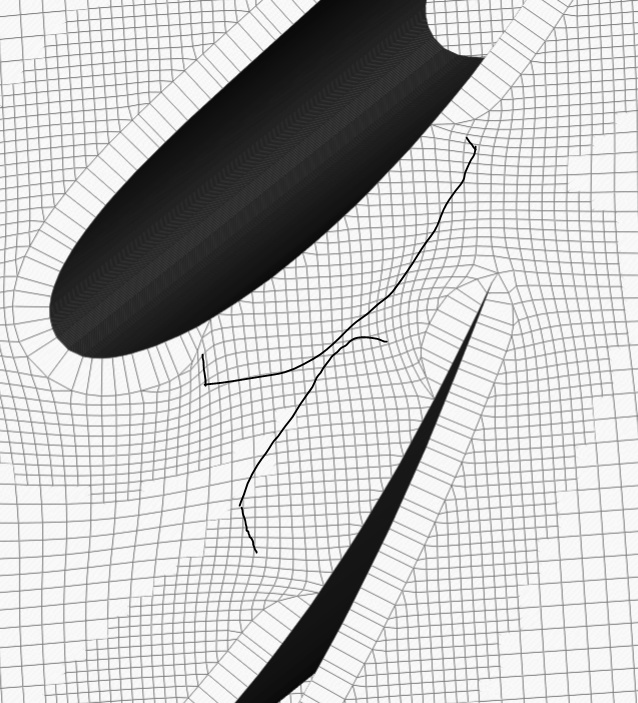
There are two main reasons for the gurney flap
- described below - it moves the flow upwards increasing downforce.
2 shown in my colored lines. The red is the camber line is without gurney flap, blue is with gurney flap. It essential creates a new camber line without changing profile shape. It is used as a quick and easy way to add down force once the aero package is built
But very inefficient in terms of drag, in my opinion a better option is to modify airfoil of rear wing and get rid of that vortex drag behind the flap…
No the reason for the test is to see how much difference in pressure and viscous drag between them. If little difference the I feel fairly comfortable using 1 layer… But for the test to be valid we need same area % layered in both.
I had some time after TV tonight so I finished the 3 vs 1 layer test that you started…
I will summarize results tomorrow, but it looks pretty promising for 1 layer in this first round testing … ![]()