In my simulation,
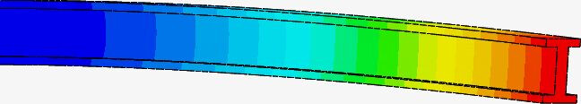
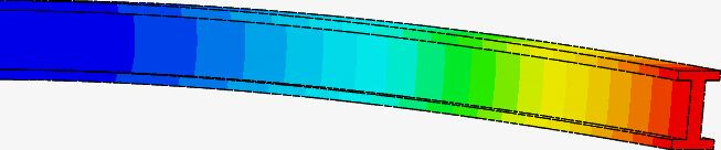
I am applying a remote force (-y 10kN) to one end face of a 10mm x 10mm x 100mm steel beam, from a position 150mm direct in front of that end face.
There are several things I don’t understand about this:
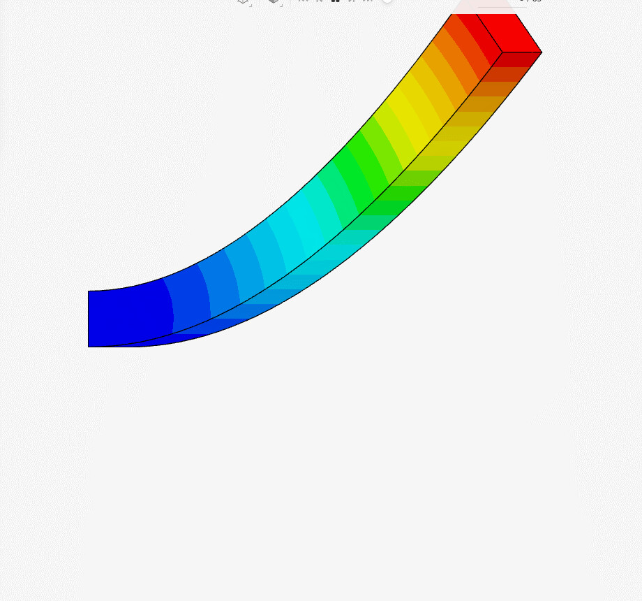
The force only acts down (as viewed) and the beam starts straight, why does it move up as well as down?
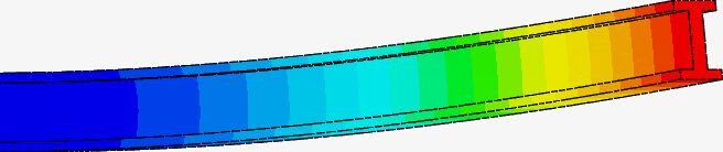
The end of the beam that is moving appears to be expanding and contracting about its own axis?
(Does anyone know of a good tutorial on the use of remote force conditions? The online help for this covers the how-to-fill-in-the-boxes, but entirely skips the why of using a remote force. and the ‘example’ shows a deformed I-beam junction, but gives no explanation of what force caused it or from where it was applied; let alone why.
What I would like to see is a worked example of a force being applied directly via member, and then the same force being applied with the intermediate member omitted. actually several examples, including remotely applied torque would be good.)
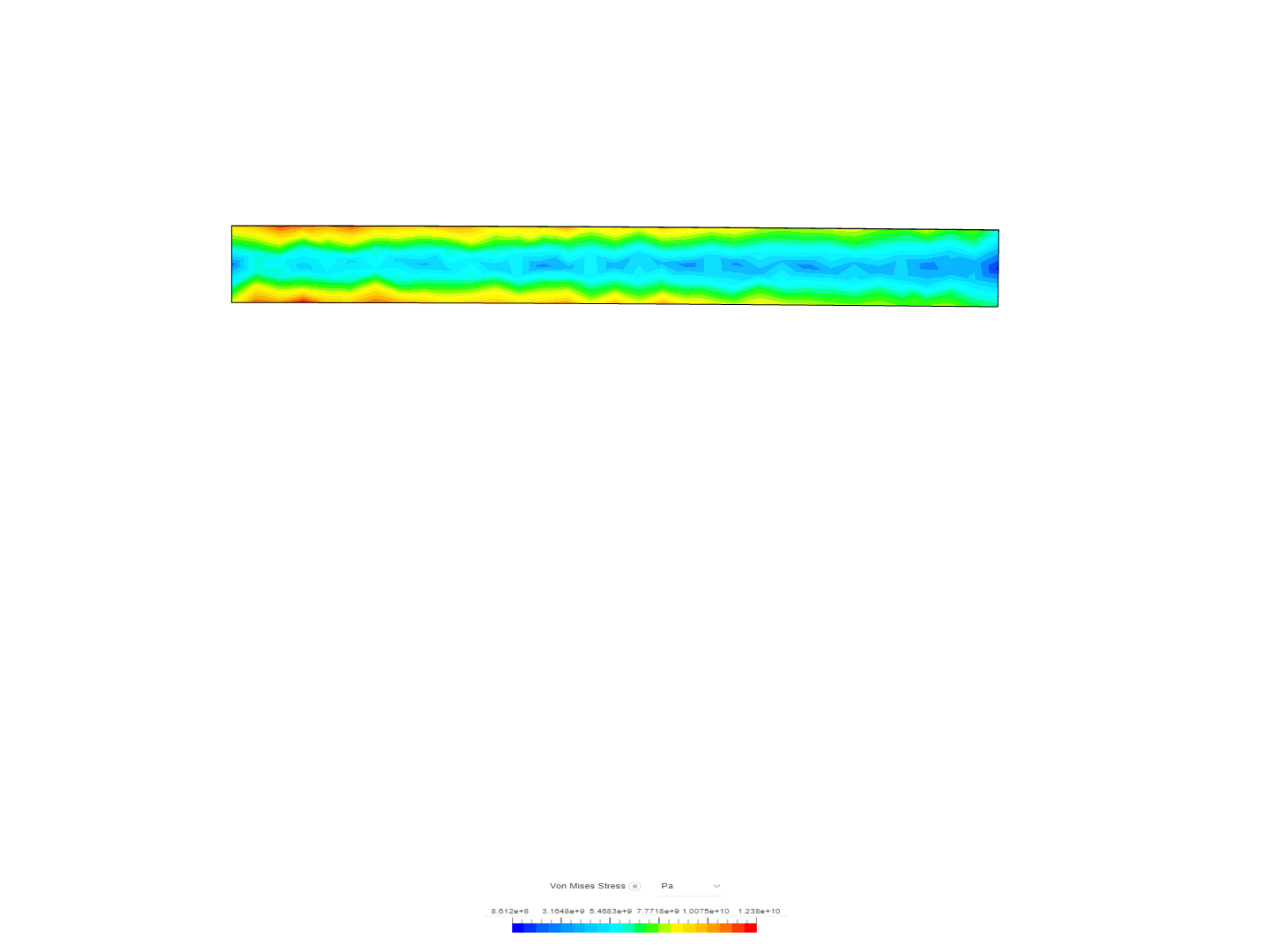
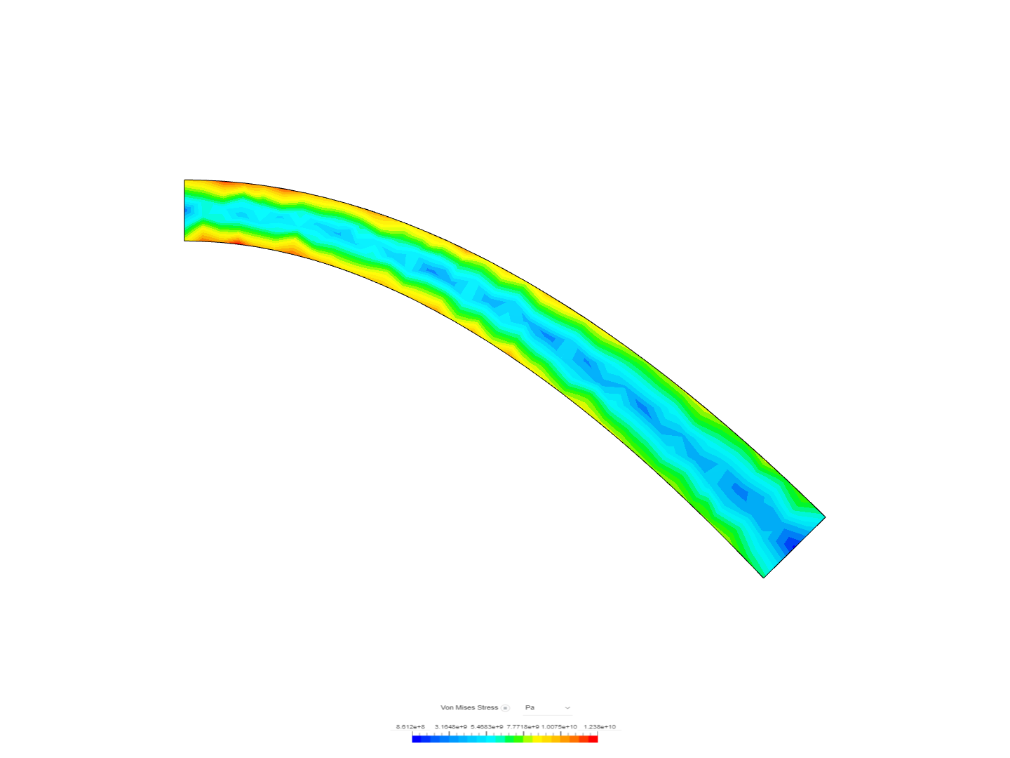
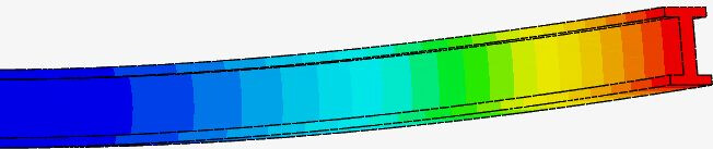
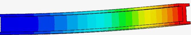
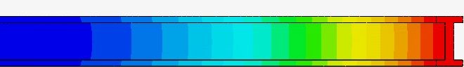
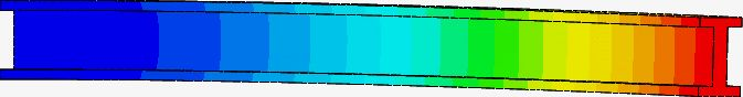
The upper image has zero displacement, meaning that this is the original state, and the other shows how one face is moved downwards (negative y-direction) The other side does not move at all.
And yes, the cross-section will be deformed as well, if that is what you are asking.
Have you checked this validation case? This could be helpful
So, the default animation does +deflection to -deflection. While this is valid for animating mode shapes where it will vibrate in both directions, for problems that are directionally loaded it is not correct. In the Animation Dialog box you have an option for Animation Type and Animation Range. By playing with these two setting you should be able to get the correct animation.
The end of the beam that looks like it’s expanding and contracting is most likely due to the fact you are scaling the results up to visually show the deformation Your images are probably scaled up 100+). When you scale the results to display you to are scaling all directions and rotations of the displacement. This can cause things to look a little too stretched out at higher scaling factors.
The remote force can be used in several ways and it mainly helps to simplify models. A classic example is someone who is analyzing a car frame. The loads from the motor are critical but you really do not care about the engine block, pistons, etc. So, in this case you would create a remote force at the centroid of the engine and tie it to the four mounting points. This creates a much simpler problem to solve.
In the case of the Beam example, it is looking at a beam under pure bending. You could model this by putting a force and a moment at the centroid of the “I” face or use a remote load that will automatically induce the correct loading on that face. In the beam example it probably does not make much difference but the beam is an easily verifiable test case.
Okay. That explains the +/- (though not the reason for it; but I guess it is useful in some senarios I’m not familiar with.)
Hm. If specifying a +ve force is animated -F … 0 … +F; and specifying a -ve force also animates -F … 0 … +F;
which half of that range does the “Half” setting give you?
And is it context sensitive?
(I know-- try it and see )
This is where the application of remote forces gets fuzzy for me. If the remote force applied to the end face of a beam represents (say) a load attached to the end of the beam, then when that load causes the beam to deflect down, I would expect the vertical cross-section of the beam to compress slightly, not bell-mouth as shown in the simulation/animation?
I get the logic of omitting complexity and speeding up runs. The bit I am having trouble with is why use a remote force, rather than just a force?
Taking your engine mount example. If you set the remote point at the CoG of the engine – hard to determine but… – then if that point is (say) londitudinally forward of the engine mount plane, does the bounday condition/software take care of the torque that this would apply to the mounts? Or do you have to apply a force for to account for the weight of the block acting under gravity; and a moment to account for the twist due to the offset between the CoG and the mounting plane?
Or another example. You have a brass hex head bolt screwed into something. You wish to test the effect of a force applied to the end of an steel allen key being used to tighten that bolt.
We all know that the allen key will not act purely rotationally. They’ll also be some off-axis forces trying to twist the allen key out of the bolt and strip the head.
So if you set the remote point to the position of the other end of the allen key and apply a force in the direction the hand would apply it – ie not exactly tangent to the axis of bolt. And apply that to the inner faces of the hex head. Will that take care of both the wanted rotational forces being applied to the bolt, and the unwanted forces acting to twist the key out of the head?