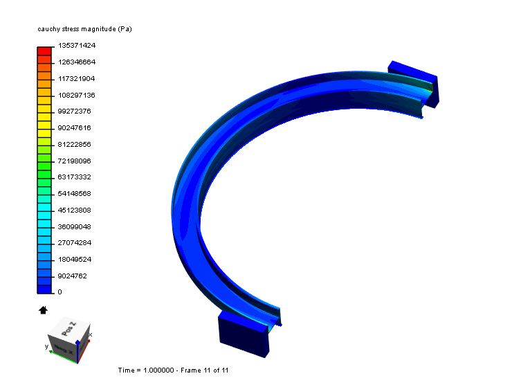
Basicly it is 1/4 a polyethylene corrugated pipe and i want to see the behaviour in large deformations. Also during tests i have deformation in square profile top of pipe. I want see as well but not at first sight.
I dont have yet plasticity spesification of PE, until this i am doing it as aliminum pipe.
My main problem is, i always have “singular matrix problem”. Probably have some problems in contact setup or boundary descriptions but somehow i could not figure it out.
We will check this out and get back to you as soon as we figured out a solution. Obligatory tagging my colleagues, the one and only @fea_squad here that might jump in here in the meantime.
Here is a list of the changes I made in order to make it work:
Mesh: second to first order, as it is more stable for physical contacts.
Mesh: refined blocks for more precise contact.
Imposed displacement and fixed condition: changed from the whole body to external face only. This can be conflicting as causes two conditions on contact faces.
Removed blocks from symmetries, as they already have imposed displacement.
Individualized physical contacts, switched master/slaves, changed solution method to Newton
Simulation control: changed number of cores to 8, as the mesh has 33k nodes.
I think the problem is not the mesh, it’s the boundary conditions,
I have changed the symmetries by manual symmetries (in two directions unconstrained) and chosen a bigger machine and has calculated well without problems.
When we have perpendicular and adjacent faces of boundary conditions , the code can generate problems because you have 2 bondarys in 1 edge, but it is solved making the manual symmetry (Is a classical problem of code_aster and FEA but not difficult to avoid)
Thanks a lot for the configuration. Actually i was trying different combinations so it was messed up :). But many thanks to you it seems really robust now. And i have tried the model with larger displacement and also with plasticity effects and it worked well. Quick question : Can you explain please the switching master/slave thing?
Now i have the next step that meterial behaviour part;
As i said my goal is modeling the polyethylene corrugated pipe and it needed to be modeled as linear viscoelastic or viscoelastic-plastic behaviour. As far as i see we dont have option in Simscale? I have some emprical equations from the literature, How can i use them here to see the required behaviour?
Thanks a lot for the response and the setup. Manual symmetry is quiet elegant solution indeed. But as i told, during trials some of other configurations was messed up. But it works slower than @ggiraldo solution. Also i compared both solutions with same BC, @ggiraldo model was more robust and seemed true, although need for a validation for sure.
It is a nice project that you have here, expect to see it finished with some explanation of the results.
Answering your questions:
It might not be totally obligatory, but I think that a contact per pair of faces is more robust. At least that is what I always try to achieve when possible. I had to switch master/slaves because you can’t have one face as slave in more than one contact definition. Physically this makes no difference, only in the algorithm.
Currently the platform supports linear-plastic (with multi-linear curve definition) and hyperelastic coefficient based models (Mooney Rivlin, Neo Hooke and Signorini). If you post your material data/equations we can evaluate if any of this models is appropriate for your case.