I´m trying to simulate waves in a channel. I created a volume representing uniform initial level adding a triangle of water in an extreme. When time begin to run triangle will fall down making the initial perturbation and the wave. Next message was emerged: “A setup with 2 regions is being used in a single-region analysis type. Please make sure that all regions except for one have an Advanced Concept assigned to them.”
Please your help with that. Could be I assigned a imported .STL with the described shape and assigned it to subdomains1 volume or other .STL representig the channel.
Many thanks in advance.
Hi @Rsotomayor ,
Could you please post the project link (URL) of your workbench, so we can have a look?
Thanks!
Thanks
Ricardo Sotomayor
Thanks!
I see that you are trying to use the water .stl file to initialize the water domain. On the other hand, this causes the simulation to fail, since a single volume should be used for multiphase simulations.
Would it be possible to use a parallelepiped instead of the triangle for the wave generation? Then you would be able to use geometry primitives (like discussed in this article) to initialize the domain.
Just as an example, here is a wave project that I posted on forums some time ago using geometry primitives.
Cheers
Hi Ricardo, I received your advice and I corrected the simulation. I noticed that he had incorrectly initialized the flow region and other things. But still the simulation could not run properly and the following message appeared “The phase fraction of your multiphase simulation went out of bounds. This may happen due to multiple reasons, mainly a too large time step, poor mesh quality or high-order numerical schemes. Please review your simulation set up and consider a smaller or adjustable time step, ensuring that the Courant number (CFL) does not exceed 1”.
Can you help me with this? URL is https://www.simscale.com/workbench/?pid=3711040128367080144&mi=run%3A10%2Csimulation%3A7&mt=SIMULATION_RUN.
Regards
Hi,
As far as I can see, I believe you were able to make some changes in the setup, preventing the simulation to fail with the error above?
On a side note, there’s quite a few mesh-related changes that you can perform, to allow the simulation to run more effectively. This page should give you more details.
Cheers
Thank you Ricardo. Your advices and links allowed me run the simulation. Regards
1 Like
Ricardo, I´ve seen Filter dialog for Solution Fields does not have option for particle traces. I suppose this is not possible in transient, isn’t it? Thanks
I can create traces just fine for my multiphase projects - is the button not available in your project?

Cheers
Of course, excuse me. Tutorial show a posibble old aspect. I’ll investigate That. Thanks
Hi Ricardo, how can i see only water phraction? Thanks
Hi, I can’t tell for sure what you are looking for just from the description.
Is it something similar to this?
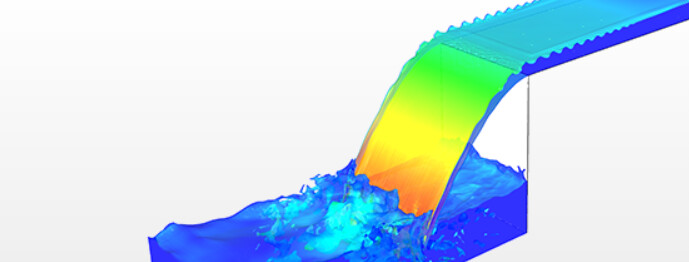
If so, you should try out iso surfaces and iso volumes, using “phase fraction” as iso scalar. For coloring, a solid color (blue) or phase fraction/velocity are usually nice-looking.
Cheers
I´m trying to see the internal movements of water particles and their velocity vectors. I have applied filters to clean vectors I don´t want see like air ones but I want to know if I can avoid air part completely.
What about iso volumes, or iso surfaces, tracking a “phase fraction” range that represents water, and plotting vectors?
Something like this:

Many thanks, Ricardo
Ricardo, I tried to find how to create a window or such inner-outlet connection, since my model is an open channel. I concluded such option is available only in convection models, no in multiphase analisis, isn’t it?
…or could be upper face of flow region been assigned with a mean value pressure?
Thanks in advance
Hi,
By window/inner-outlet connection, do you mean a free path, where flow can go in or out of the system? (not sure if I understood the description correctly - sorry).
If that is the case, it’s possible with custom boundary conditions - something like in this project:
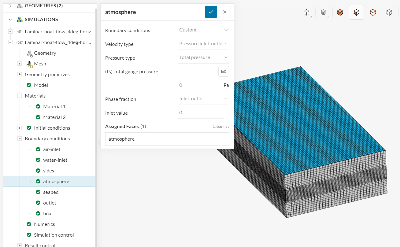
It’s an open boundary condition, allowing fluid to go out of the domain freely, and setting the fluid to air (phase 0 for the “inlet value”) if there is any fluid going in.
Thanks Ricardo, very clear.
Ricardo, intent to create mesh failed because following message: There were no compute instances available that matched the requested capacity. Please try again in a few minutes.
Could you please tell me if this is a set up problem or only I have to waite? The case URT is https://www.simscale.com/workbench/?pid=5645947974614846830&mi=spec%3A20fdc2d7-e121-4fbf-8bc4-18fb04340460%2Cservice%3AMESHING%2Cstrategy%3A9&sh=8.
Many thanks
Ricardo, I’ve been stuck in mesh generation step. Previous geometry suppousely failed because Rotating Zone enter in the two fraction zones, water and air. I modified geometry to avoid this but meshing failed now with this message: The mesh may be too coarse to resolve the geometry in specific areas. Refine the mesh or contact our support for assistance.
Can you help me please. RTU is https://www.simscale.com/workbench/?pid=4148381304401920262&mi=spec%3Ab84b1ced-83eb-47e5-a094-4392149402df%2Cservice%3AMESHING%2Cstrategy%3A4&sh=3
Thanks