Hello, I’m new using this software and I’m trying to do a simulation of an axial flow pump. It is composed by a rotor, a stator, a pipe which is where the flow will go out and finally a fake reference volume that I use to assign the inlet boundary condition.
When I run the simulation I found the following error: A multi-region mesh was assigned - this analysis-type requires a single-region mesh.
I’ve assigned to the rotor the mrf rotating zone and to the pipe and the fake reference volume the passive volume source but I still got problem in the simulation. Anyone kindly can help me.
Hello!
For simulations with rotating zones, our geometry needs to have 2 volumes:
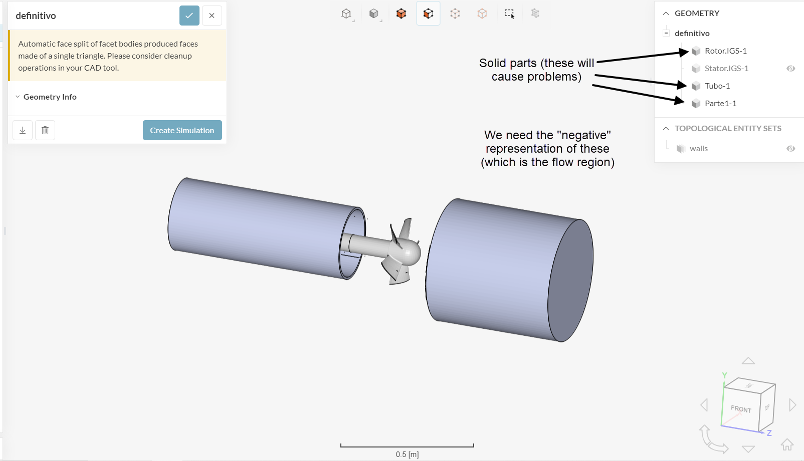
1 - Flow region (volume representing the fluid domain)
2 - An additional volume, representing the volume that will be spinning
With that being said, the actual solid parts of the geometry are not desired, otherwise we run into multi-region mesh issues.
So basically, you need to create the flow region locally, in your CAD software, and use a Boolean/Combine operation in Cut/Subtract mode, to remove the solid volumes from the flow region.
Note: the rotating zone should be an additional volume. It doesn’t cut through the flow region: the flow region and the rotating should fully intersect with each other.
Make sure to check the following docs for more notes:
- How to Prepare the CAD for Simulating Rotating Zones | SimScale
- How to Prepare the CAD for Simulating Rotating Zones | SimScale
Cheers
1 Like