Hi Jousef,
When do you think the issue will be resolved? Because as you know all our FS deadlines are very tight.
Also this is the link to my project that I am struggling with like Dan:
Best,
Tina
Hi Jousef,
When do you think the issue will be resolved? Because as you know all our FS deadlines are very tight.
Also this is the link to my project that I am struggling with like Dan:
Best,
Tina
Will get back to you as soon as possible guys, let me check with the CAD engineers.
Best,
Jousef
I believe i have stumbled upon the answer to the volume question, although i wasnt attempting to solve it.
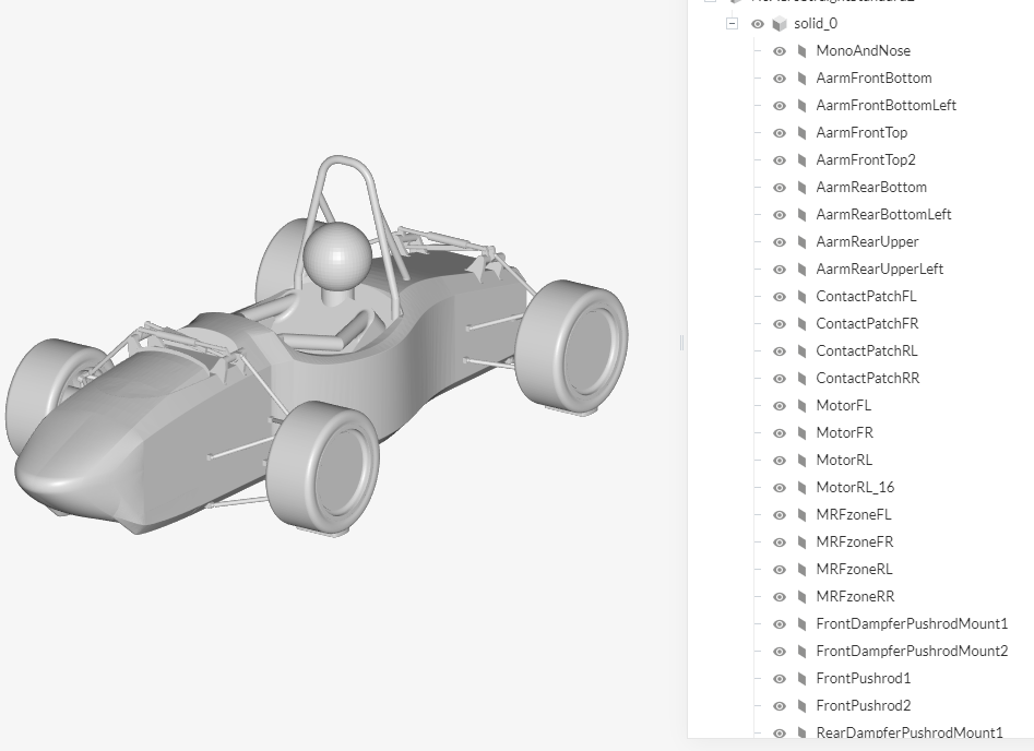
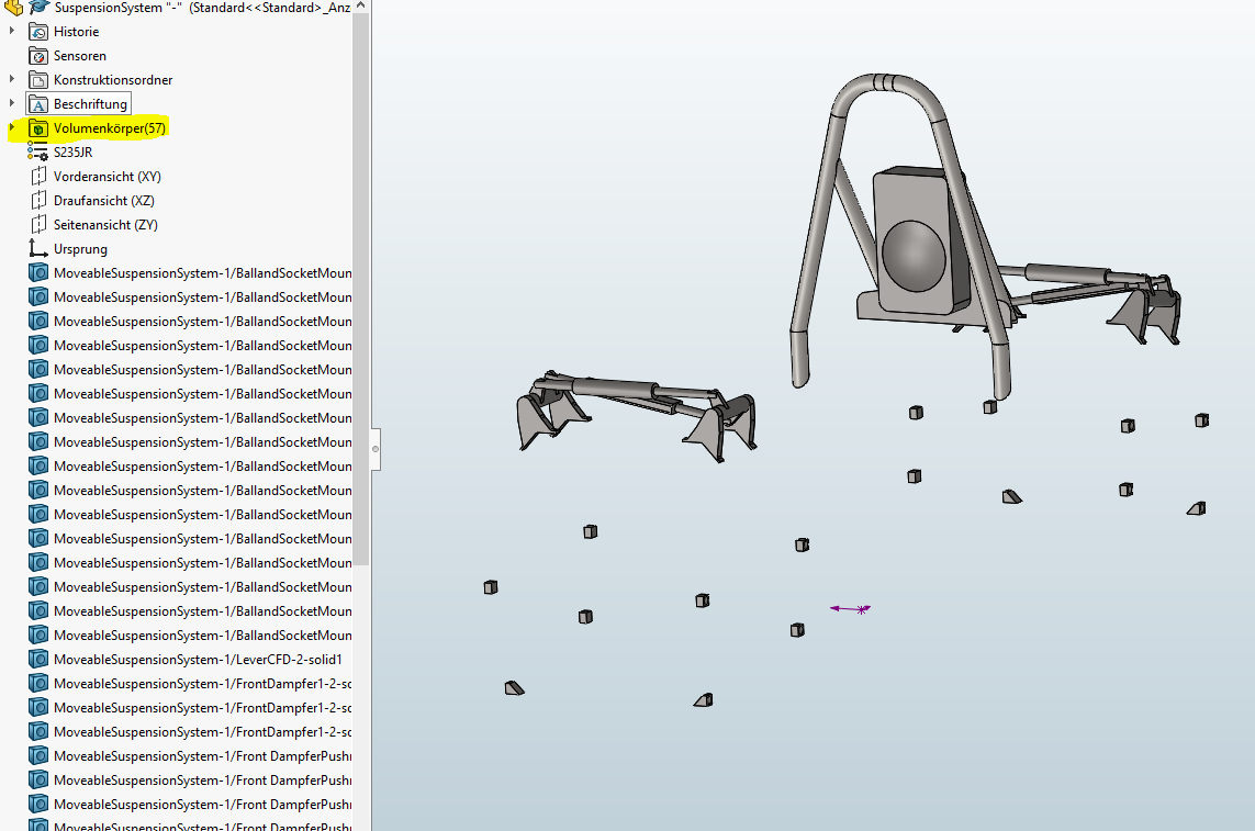
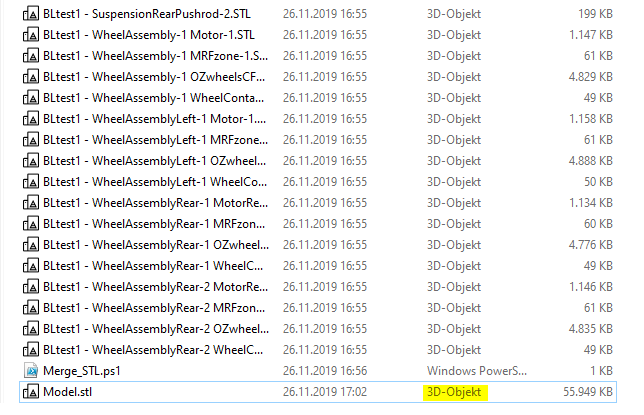
I was trying to do some quick meshing to see the effects of different boundy layer settings (i want to have a good representation of the Y+ value between 30 and 300) and i used the merging script provided by simscale as this saves a lot of time. The merging script just throws all the STLs together but creates a 3D object file as the output shown below.
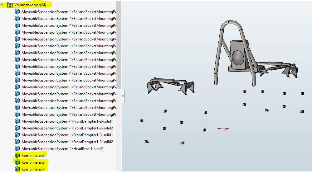
Normally i merge everything by hand in notepad so all files are saved as TXT files, which i believe converts the face selections to solid bodies. This is shown in the next picture where i merged everything manually and the drop down menu for each entity in the tree is now gone.
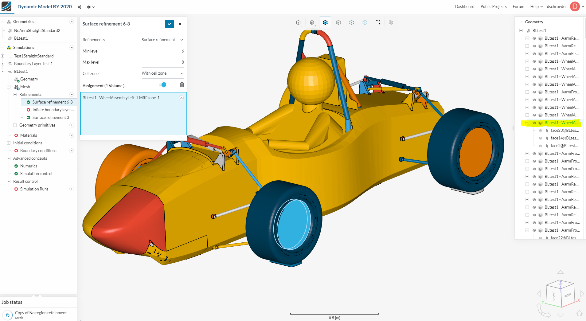
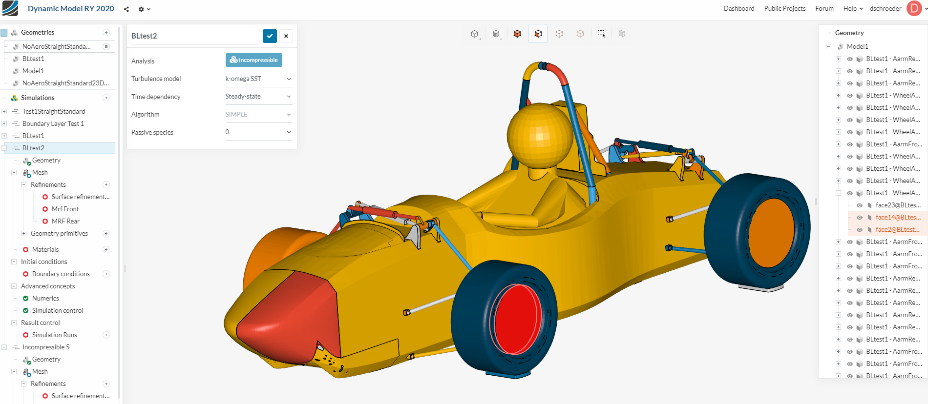
This can be seen under the highlighted MRF zone in the picture. This object is recognized as three faces, which, when combined are classified as a volume. This is shown in the next picture.
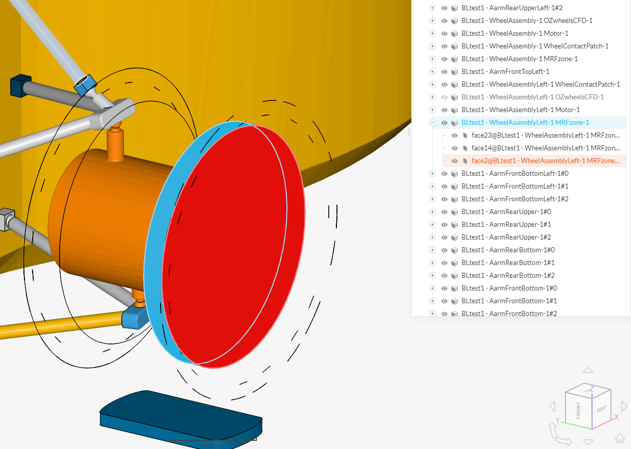
The MRF zone is now classified as a volume. In the next picture, it is shown with tire removed, that these three faces are:
these three faces when selected together create the volume that is needed to have a functioning MRF zone (so i hope)
I will be doing a simple mesh now to confirm this.
Hope this helps
Dan
Would be very happy to know Dan - keep us updated.
Something we definitely changed is that cell zones are not allowed on sheet bodies anymore, so it needs to be a closed surface. (@tinaalim & @dschroeder)
Best,
Jousef
My geometry includes closed surfaces and no sheet bodies, but the error is generated because the solver refuses to generate mesh zones using faces. What can I do?
Are you saying not to use the SimScale merger and use alternative methods?
Hey Tina,
Let me check that and get back to you!
Jousef
My colleague said that you should be able to select a volume. The cell zone must be a region on its own.
If your model has one region (volume) only and you want part of it to be a cell zone you need to modify the model!
Best,
Jousef
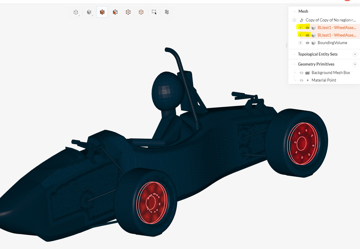
So confirmed that this method did in fact create a mesh for the MRF zones.
However I was wrong that the file upload type (3D object or txt document) was the culprit for not allowing volumes.
@tinaalim this is for you.
This is the 3D object file (merged using the merging script) with a working MRF zone mesh
I then uploaded the exact same file as a txt document, - NOT 3D object - and got the same ability to select volumes
**This is the txt document file (merged using the merging script) **
notice how the ability to select multiple faces in the selection tree (as in a volume) is still available.
I then uploaded my original non-working MRF zone file - self merged - as a 3D object file.
And as you can see … the tree pane shows everything as a solid body again. So this 3D uploaded file, self merged, will not be able to have volume selection.
So in the end it appears to have something to do with how the STL file is merged together before upload. Maybe it has to do with the fact that I renamed all the files - within the txt document - and this somehow changed the file to only being a solid body. This is my only guess as the merging script does not change any names within the individual files. It just throws everything together,
I will try a new STL merged file - with changed names within the individual part file but not with the MRF zones to see if the selection tree allows for volume selection.
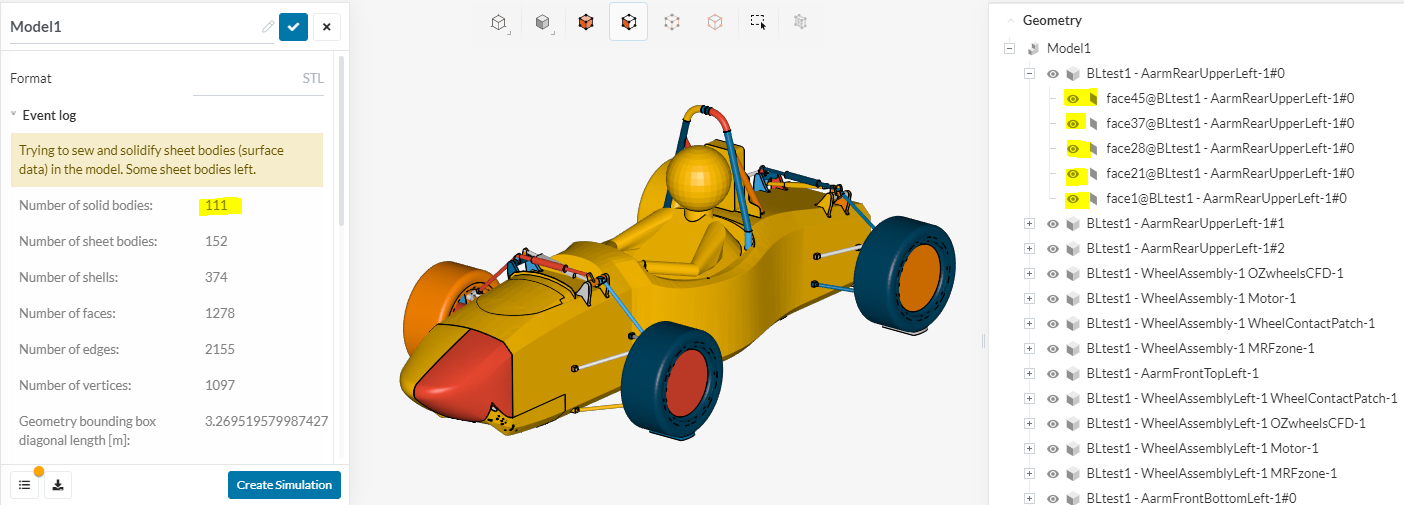
@jousefm ok now im really confused. I have tried to replicate my previous upload so that i can get the model to have volumes or “solid bodies” as shown here
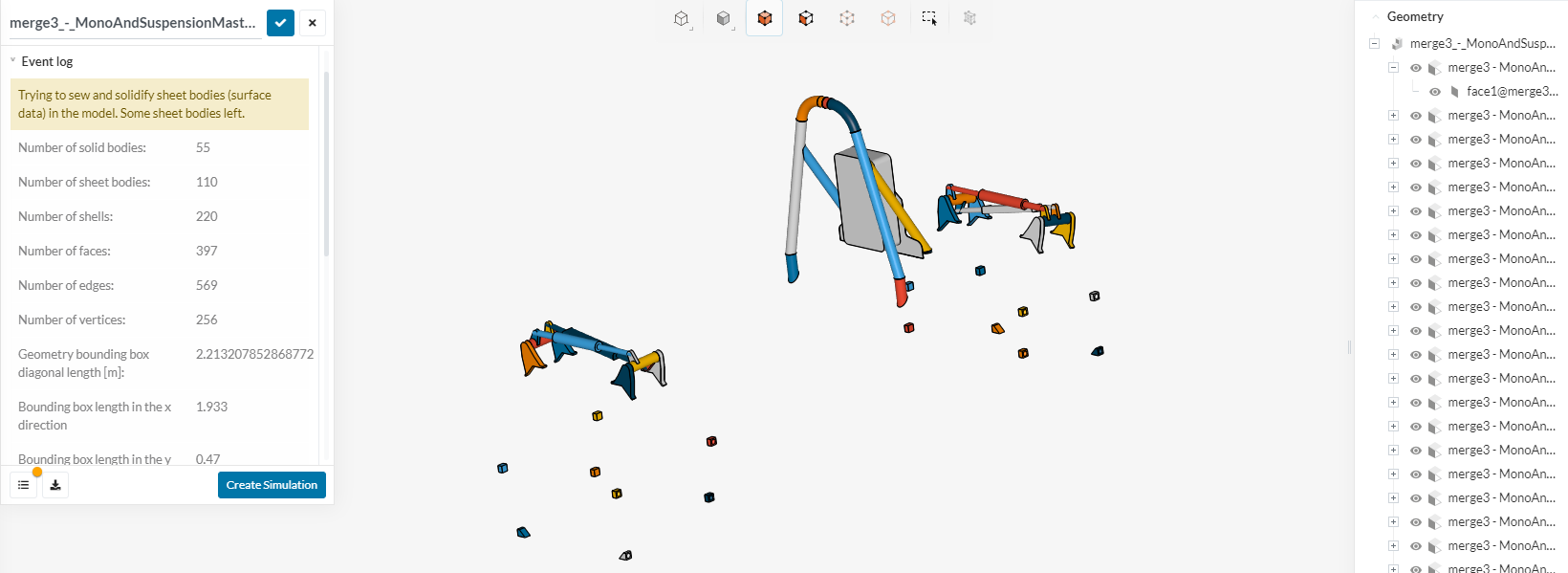
This is the “colorful geometry” and shows that solid bodies are being identified as well as sheets, shells, faces, edges, verticies. This file was created using the script merger without any name changes.
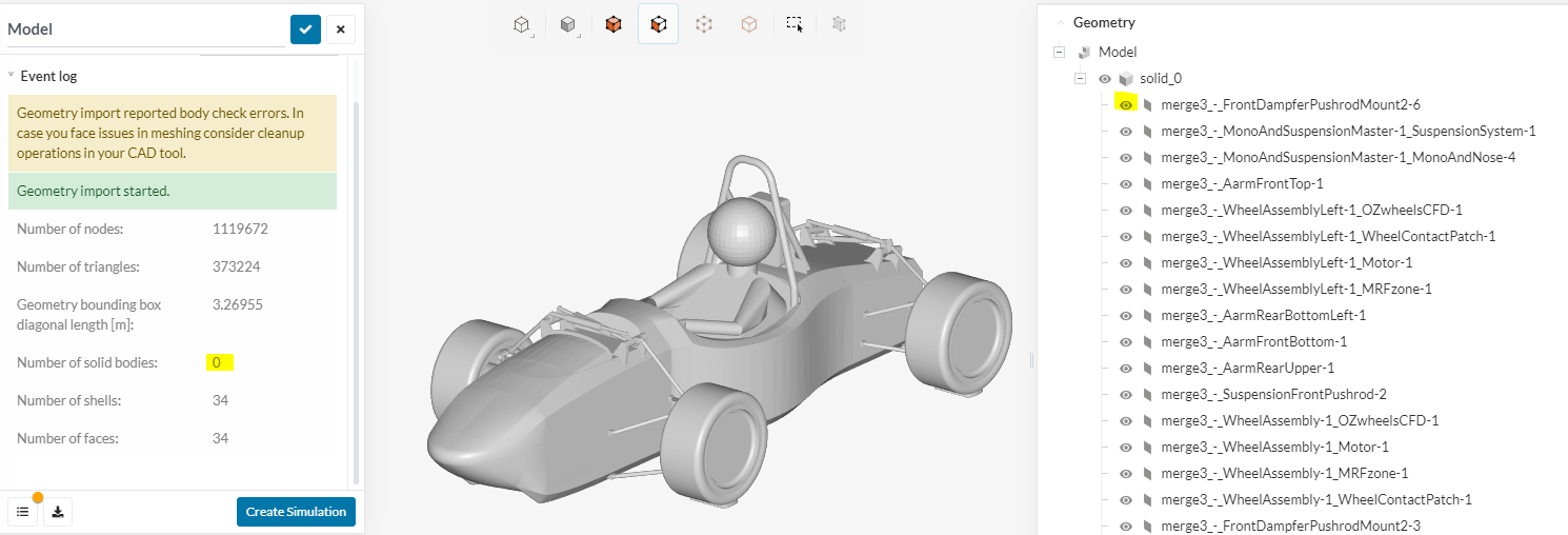
Now i am trying again to use the merger, no name changes at all, and i keep getting the old “grey geometry” where i cannot sellect volumes. This one has no solid bodies detected, only shells and faces.
How do I need to upload the file so that solid bodies are detected. Should i not use STLs anymore? What would you reccomend for this simulation application?
Thanks,
Dan
I tried replicating your process too and I didn’t notice any changes. Sometimes the merger gives me volumes but more often than not it’s all faces.
Hello, my suggestion is to clean the model in the first place. In both cases (colorful and shades of grey), sheet bodies are present, indicating that some faulty entities cannot be fixed.
Let me know how I can be more helpful
Edoardo
@Edoardo thanks for the suggestion but for our mono it is a bit hard as the solidworks file wasnt created by me. It is was made 3 years ago by old team memebers and i would have to completely re-create it, which i might have to do. However i have done some more tests which just bring up more questions.
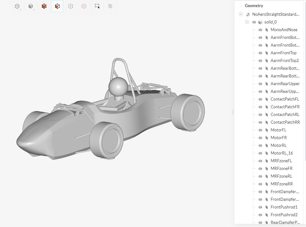
First i tried to do just a simple part of the car to see if it would be recognized again as a solid body
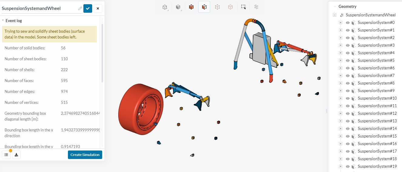
this is just the suspension system uploaded as an 3D object file - no name changes.
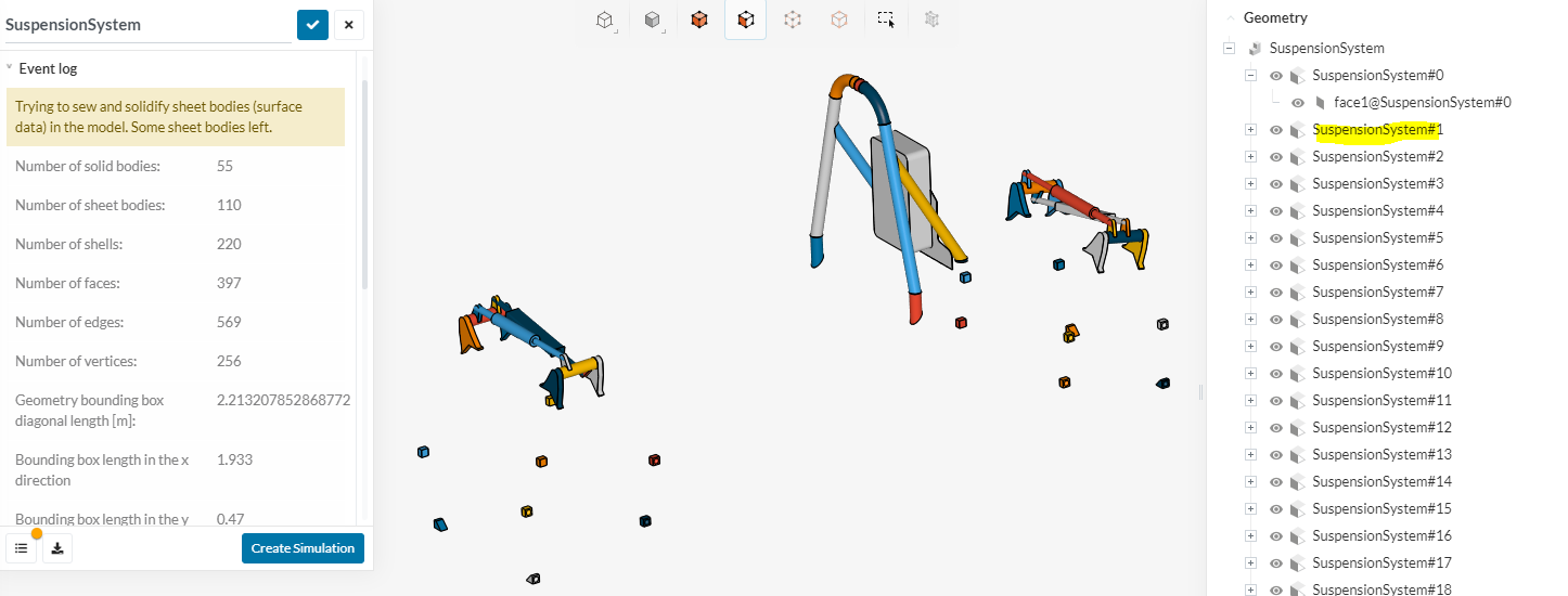
The exact same result happened when i uploaded a TXT file with a name change in the suspension system. notice the name change in the selection tree
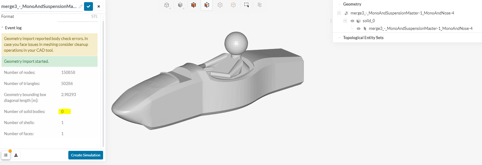
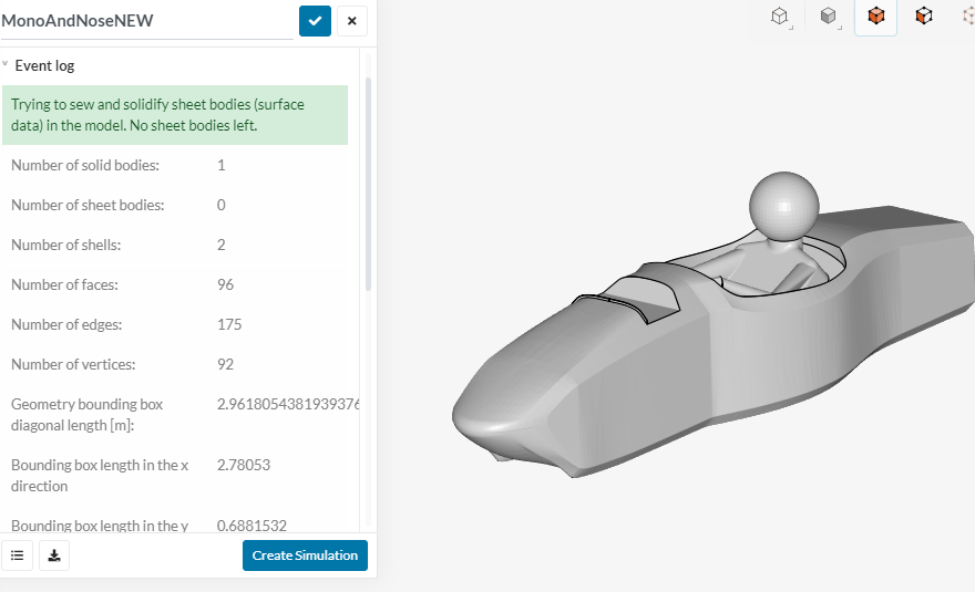
based on this i uploaded just the monocoque file. Back to no solid body
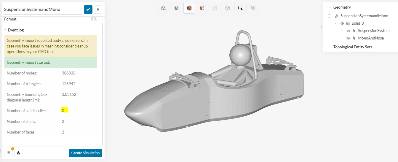
Now i tried merging both these files to see what happens … both now change to no solid body
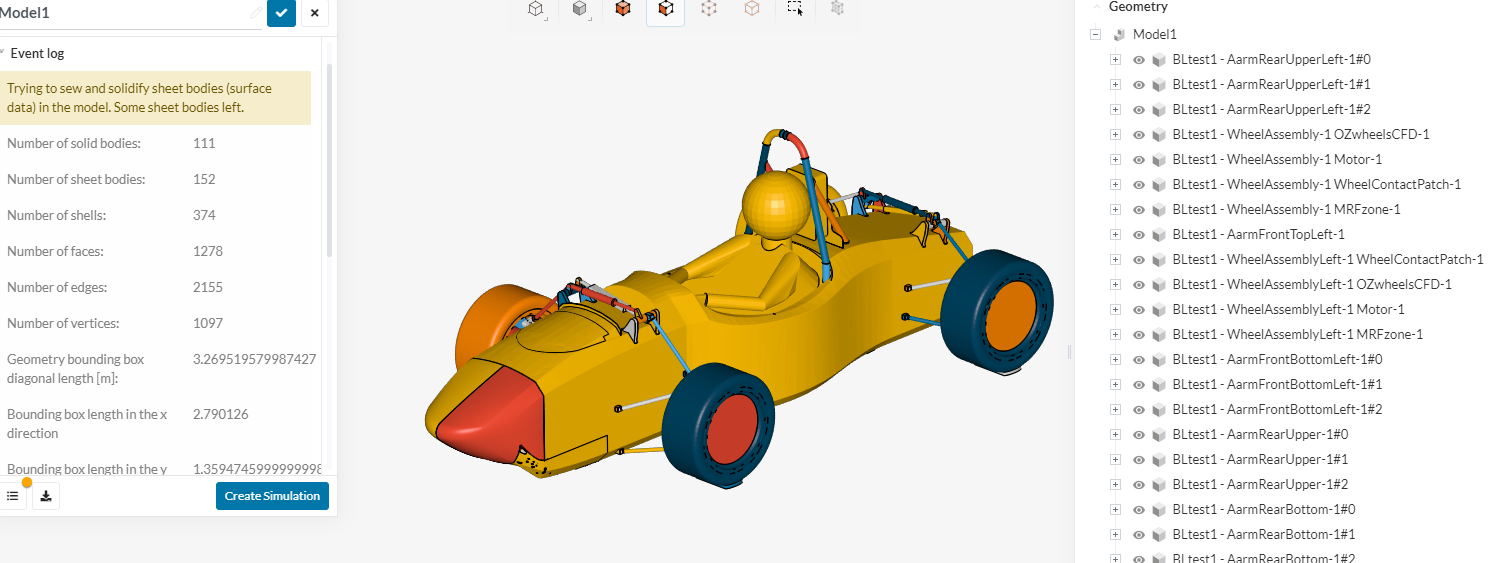
And lastly I tried merging the suspension system with a random part, this case a tire. Both changed name, both TXT file upload. now its back to solid body.
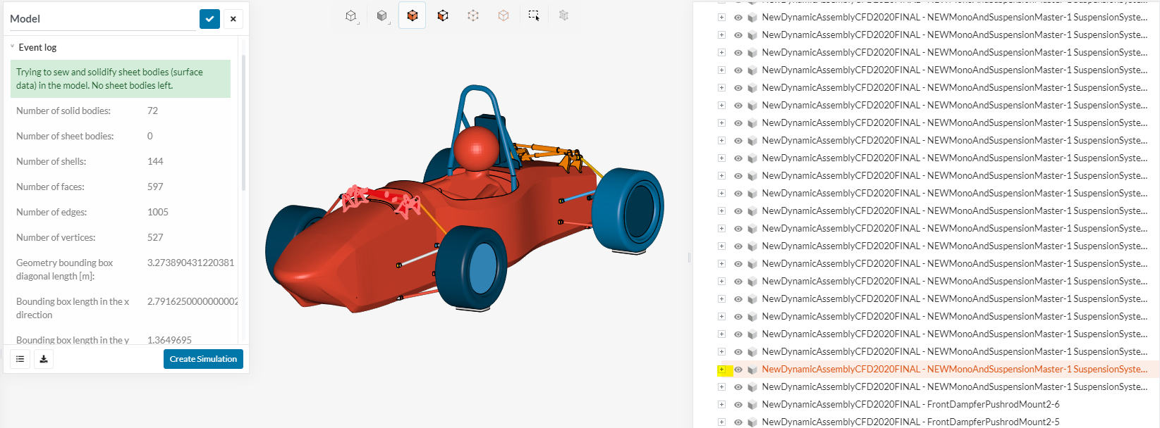
Now obviously this leads me to believe that the MONO file is to blame. However the mono has already been accepted with solid bodies before, which i also showed in prevoius posts. The solidworks file hasnt changed. Here it is.
This was from the 3D object vs TXT test. I really dont understand why it seems to choose when to accept the file as a solid body or not. Any help would be appreciated.
Dan
Dan, as harsh as it might sound. Relying on the model from a guy 3 years ago is (IMHO) not the best thing. From my experience, doctoring ones files can be more daunting than creating your own with a clean approach.
I personally would remodel it and also make sure to choose either a bottom-up or top-down approach for your modeling and track everything in a system of your racing team where everyone has access and can really understand the process on how the car has been designed.
Hope that makes sense.
Jousef
Yea that would be much better i agree. Last year there were no problems with this mono and up until this MRF zone change, there would have been no problem this year. If the mono was the true cause, then why was it accepted in earlier geometry uploads? I will be working more with this mono file to see if i can find the reason. I agree that at a certain point it makes more sense to redo it. However it is dependent on several assembly files which adds even more work on top. Ill post any results i find
Dan
I agree with Jousef.
Importing a model in Simscale is now stricter than before, in order to exploit new features e.g. the new standard mesher.
I would spend an afternoon to model the car again in Solidworks. Also, if you’re using this tool, there’s no need to save the file as an STL, we support the native Solidworks format
Sorry to dissapoint, I got in yesterday and I new it would be faster to recreate the whole thing. Which was still 10hrs of work haha. But I did finally get my first time that a geometry uploaded without errors. That green box made me happy.
So the mono did end up being the main problem.
Also, I originally wanted that the suspension system (dampers, main hoop, ball joint attachemts) could be selected all as one part but this is no longer allowed as the STL still picks up all bodies in the CAD part even though it is one part file.
However, using the combine feature in soldiworks merges all the main bodies together so that its a bit less selection work in simscale
It is still annoying that it cant be selected as one body, this makes surface refeinment selection much quicker. There are so many suspension parts to select now but i guess its not that bad. Group selecting isnt that hard to do.
Thanks for all the help @jousefm @DaleKramer @Edoardo during this. Now onto the next big project of mesh quality. I will most likely be asking for help with that too haha, but ill make a new thread.
Dan
I FINALLY FOUND A SOLUTION TO MY PROBLEM!!
My geometry was showing up grey and as one surface because one of my components had multiple holes in the geometry. Since I was preparing my geometries in CATIA by creating surfaces and closing them to be solid, this was causing issies with geometries being hollow as well. To fix the issue and locate the problematic component, I uploaded my STEP file onto Solidworks. The faulty faces immediately showed up. I created new faces and fixed my geometry there and exported the individual stl files. The problem was then fixed and I no longer got a singular surface when I uploaded my geometry onto SimScale.
Hope this helps everyone who has been struggling with the same issue as me!